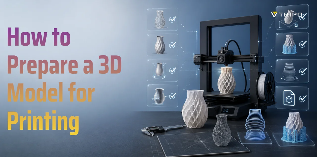
How to Prepare a 3D Model for Printing: A Complete Step-by-Step Checklist
TL;DR
- A print-ready model needs proper wall thickness, scale, orientation, and supports.
- Watertight mesh prevents slicer errors, missing layers, and failed prints.
- Slicer previews help catch hidden problems before wasting material or time.
- FDM and resin printing require different preparation for strength and support.
- Tripo AI can generate a 3D starting mesh from text or images; inspect and prepare it for your printer before slicing.
A 3D model can look perfect on screen and still fail on the printer. Thin walls may disappear, hidden holes can confuse the slicer, the scale may import incorrectly, and unsupported overhangs can warp or collapse mid-print. That is why learning how to prepare a 3D model for printing is just as important as designing the model itself.
This checklist walks through the full print-preparation process: choosing the right software, building in correct wall thickness, making the mesh watertight, setting scale and units, orienting the model, adding supports, choosing export formats, repairing files, and running slicer checks before printing. If you do not have a model yet, an AI 3D model generator such as Tripo AI can generate a 3D starting mesh from text or images. Inspect and prepare that mesh for your printer before slicing.
Choose the Right Software for Your Workflow
The best workflow depends on what you are making. Beginners may prioritize simplicity, product designers may need accurate dimensions, and sculpted or scanned models may need stronger mesh-control tools. If you need a base model quickly, AI generation can also be a useful starting point.
| Workflow Type | Best For | Validate Before Printing |
|---|---|---|
| Beginner-friendly browser modeling | Simple shapes and early concepts | Check solid geometry, units, and slicer preview |
| DCC or sculpting software | Organic shapes and custom meshes | Check manifold geometry, internal faces, and thin features |
| Parametric CAD | Functional parts and dimensioned designs | Check export scale, fits, and critical clearances with a test |
| Tripo AI | Creating a 3D starting mesh from text or images | Inspect topology, scale, wall continuity, orientation, and supports |
For brackets, boxes, and mechanical parts, use a dimension-focused CAD workflow. For sculpted or decorative objects, use a workflow with strong mesh-editing controls. For early concepts, a beginner-friendly browser workflow or Tripo AI can help create a starting mesh; every workflow still needs the same printability checks.
Design Principles to Build In from the Start
Good 3D printing preparation starts before export. The more print-friendly your design is from the beginning, the less fixing you need later.
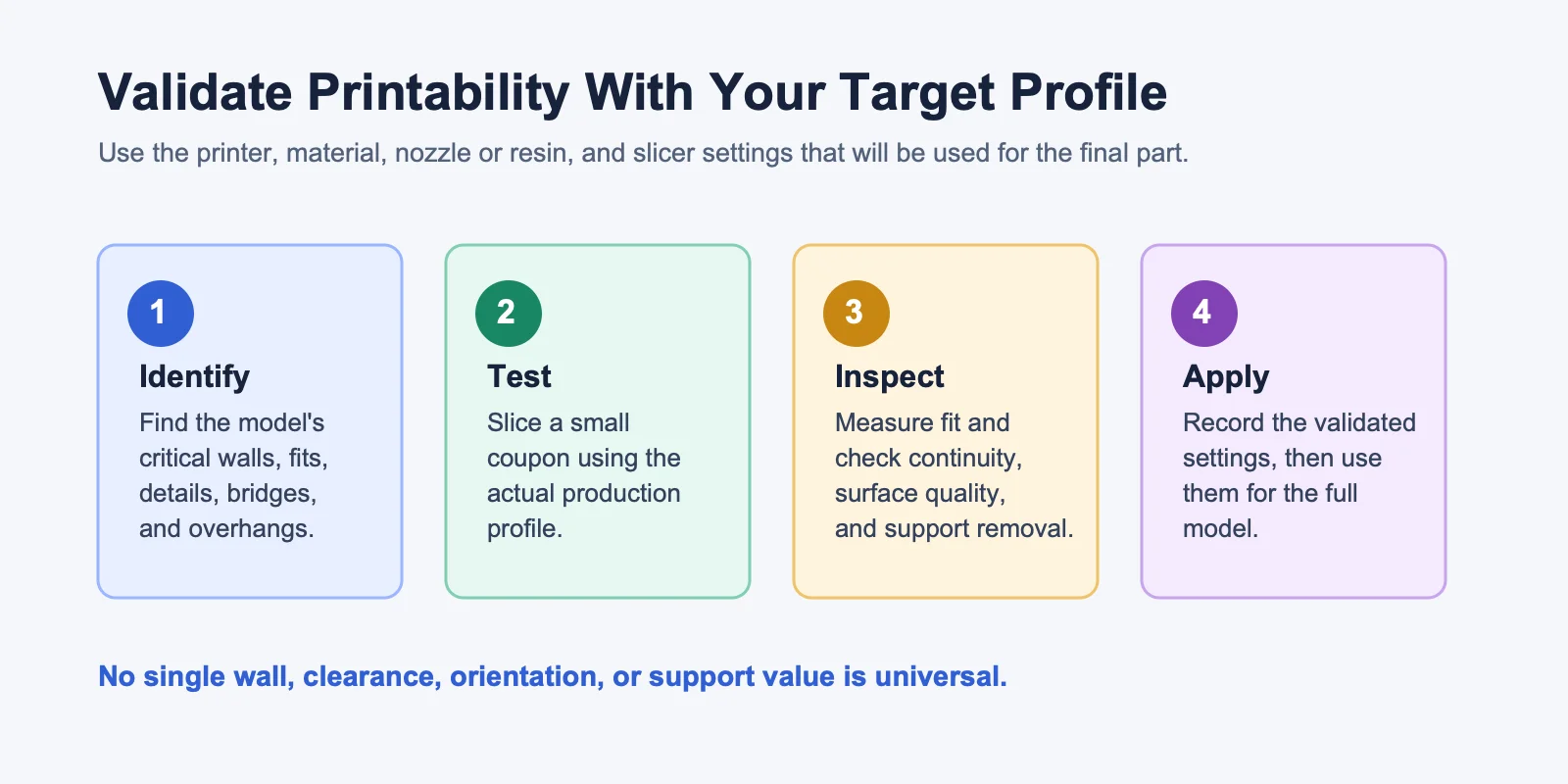
Profile disclaimer: This guide does not provide universal printing specifications. Confirm every parameter with the documentation for the selected printer, material, nozzle or resin, and slicer profile, then validate critical features with a small test before the full print.
Wall Thickness
Set wall thickness from the printer and material documentation for the production profile, then verify it with a small test that includes the thinnest wall in your model. Inspect the result for continuous walls, strength, and post-processing durability before printing the full part.
Overhangs
Overhang capability depends on the printer, nozzle, material, cooling, layer settings, and part geometry. Use the slicer preview and a small overhang test to find the unsupported geometry your production profile can handle. Redesign difficult areas with chamfers, curves, or supports where needed.
Tolerances for Fits
If parts need to fit together, design clearance into the connection and validate it with a small fit coupon using the production profile. Measure the printed result, record the clearance that works, and apply that result to the larger assembly.
Feature Size
Set minimum feature size from the target printer, material, nozzle or resin, and intended use. Print a small detail test for thin decorative elements, text, and delicate features, then increase the feature size or reinforce it if the result is incomplete or fragile.
For AI-generated or scanned models, geometry quality matters too. Tripo AI’s Smart Mesh feature is designed to generate clean, optimized topology; still check wall thickness, watertightness, scale, and supports for the target printer.
Make Your Mesh Watertight (Manifold)
A watertight, or manifold, mesh behaves like a closed solid object. Every edge should be shared by exactly two faces, with no holes, duplicate faces, floating pieces, or non-manifold edges.
Slicers treat models as solid volumes. If the mesh has gaps, the slicer may misread inside and outside areas, causing missing layers, broken walls, or strange infill.
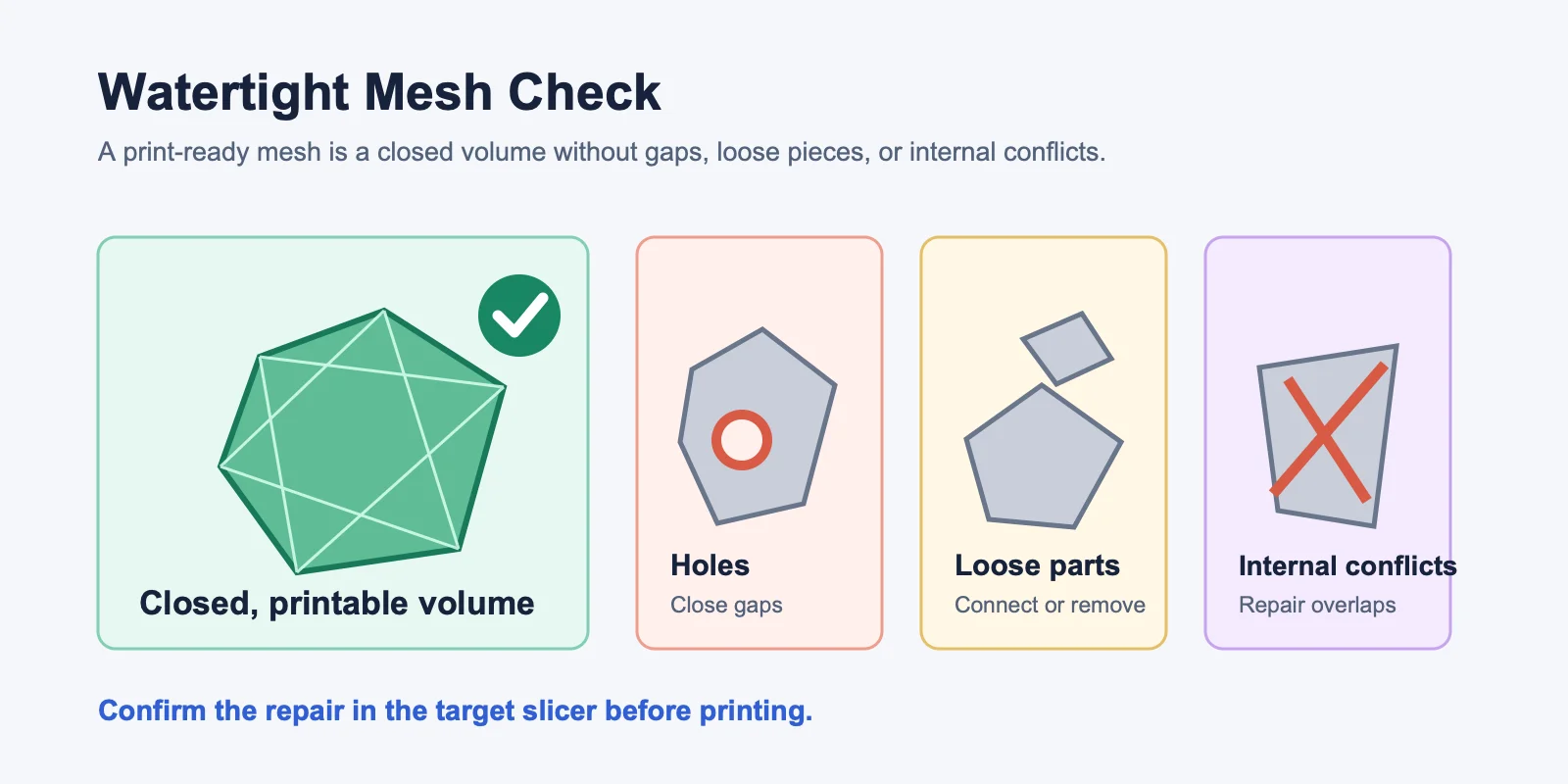
Common causes include Boolean operations that leave internal faces, imported models with holes, duplicate vertices, and overlapping surfaces. These issues may be hidden in the modeling view but appear after slicing.
Use these tools to check the mesh:
- Modeling software analysis: Use the mesh-analysis features available in your modeling workflow to locate non-manifold edges, intersections, and thin areas.
- Mesh-repair workflow: Use a repair tool to identify holes, flipped normals, duplicate surfaces, and broken regions, then inspect the repaired result.
- Slicer import check: Import the file into the target slicer and review any geometry or repair warnings before slicing.
For watertight mesh 3D printing, remember: the model must be a closed solid, not just a surface that looks solid.
Set the Correct Scale and Units
Many first prints fail because the model imports at the wrong scale. This usually happens when the modeling workflow and slicer interpret units differently.
Use this quick scale checklist:
- Confirm the unit convention required by the target printer workflow before export.
- Use the same unit convention consistently in the modeling tool, export dialog, and slicer.
- Check the model bounding box against the intended finished size before export.
- Verify the imported X, Y, and Z dimensions in the target slicer before printing.
Use a known reference feature or calibration object, compare its intended dimensions with the slicer reading, and print a small sample before committing to a full-scale part.
Orient Your Model for Printing
Print orientation affects strength, surface quality, support material, and print time. Choose the direction based on what matters most for the part.
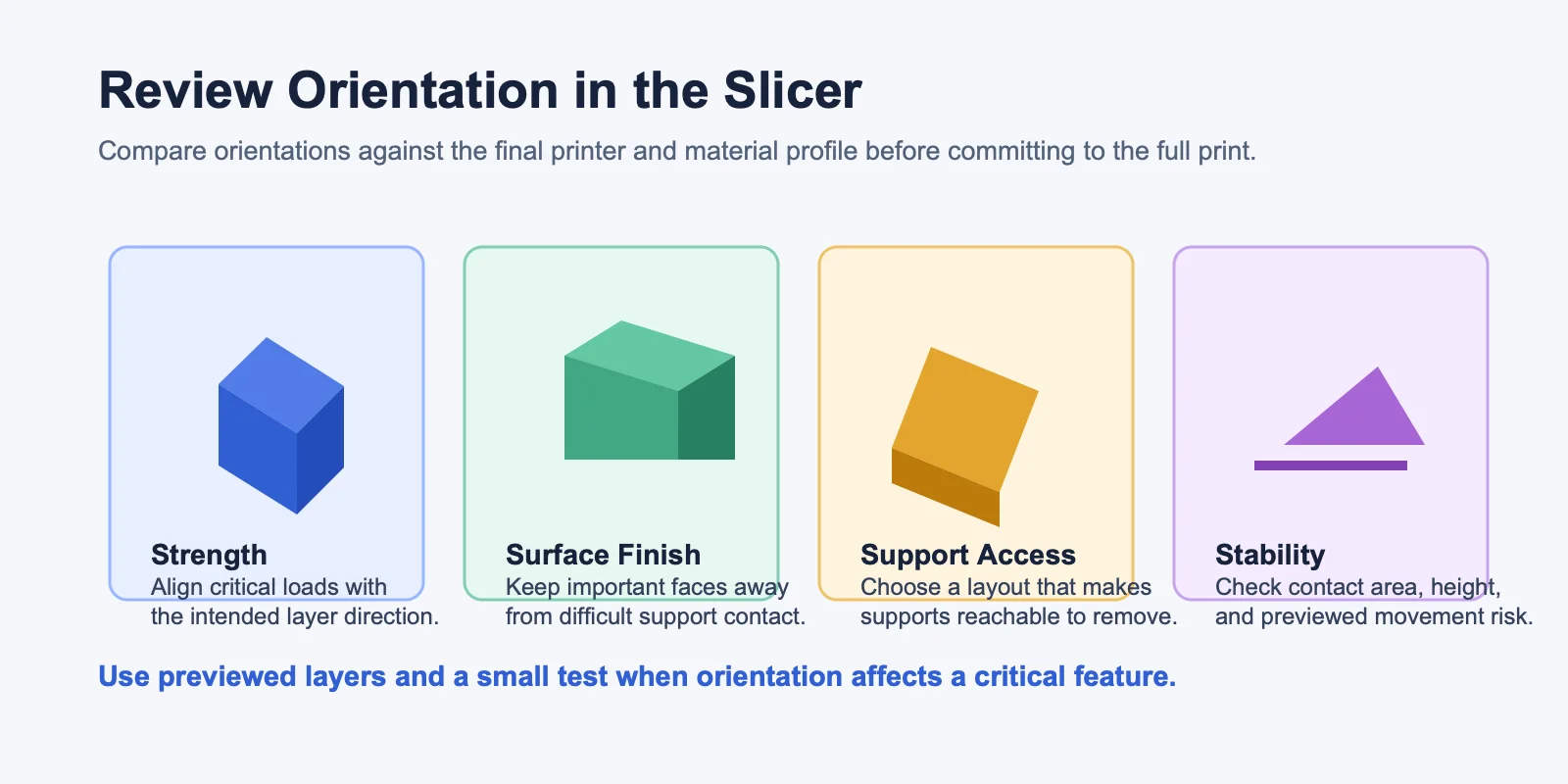
For strength: FDM parts are weakest along the Z axis, so orient load-bearing areas along X/Y when possible.
For surface quality: Place the most visible face where it avoids heavy support scarring. Build-plate faces are usually flattest, while top surfaces often print cleaner than steep angled walls.
For fewer supports: Rotate the model to reduce difficult overhangs, then verify the result in the slicer preview and with a small test when the feature is critical.
Tall, thin models may wobble or tip, so consider laying them down, tilting them, adding a temporary base, or splitting them into parts. A flat base usually improves stability and reduces warping.
Adding and Optimizing Supports
Supports hold up areas the printer cannot build cleanly in mid-air. Start with your slicer’s preview and test profile: the angle, bridge length, and horizontal opening size that need support vary with the printer, nozzle, material, cooling, layer height, and part geometry.
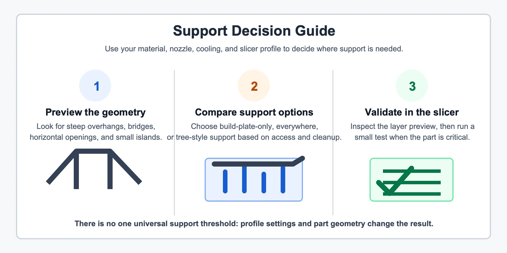
Common support styles include touching buildplate only, which can simplify removal, and everywhere supports, which can reach more areas but may create more cleanup. Compare the available support styles in preview for the specific model and production profile.
You can reduce support needs by chamfering overhangs, using self-supporting arches, splitting the model at natural seams, or adding hidden flat surfaces for easier orientation.
For resin printing, supports may need manual placement to manage peel forces and protect fine details. Generate supports in the target slicer, inspect every contact point, and validate the result for the selected resin and printer profile.
Choose the Right Export Format
Export format matters because slicers read file types differently. The main options are STL, 3MF, and OBJ.
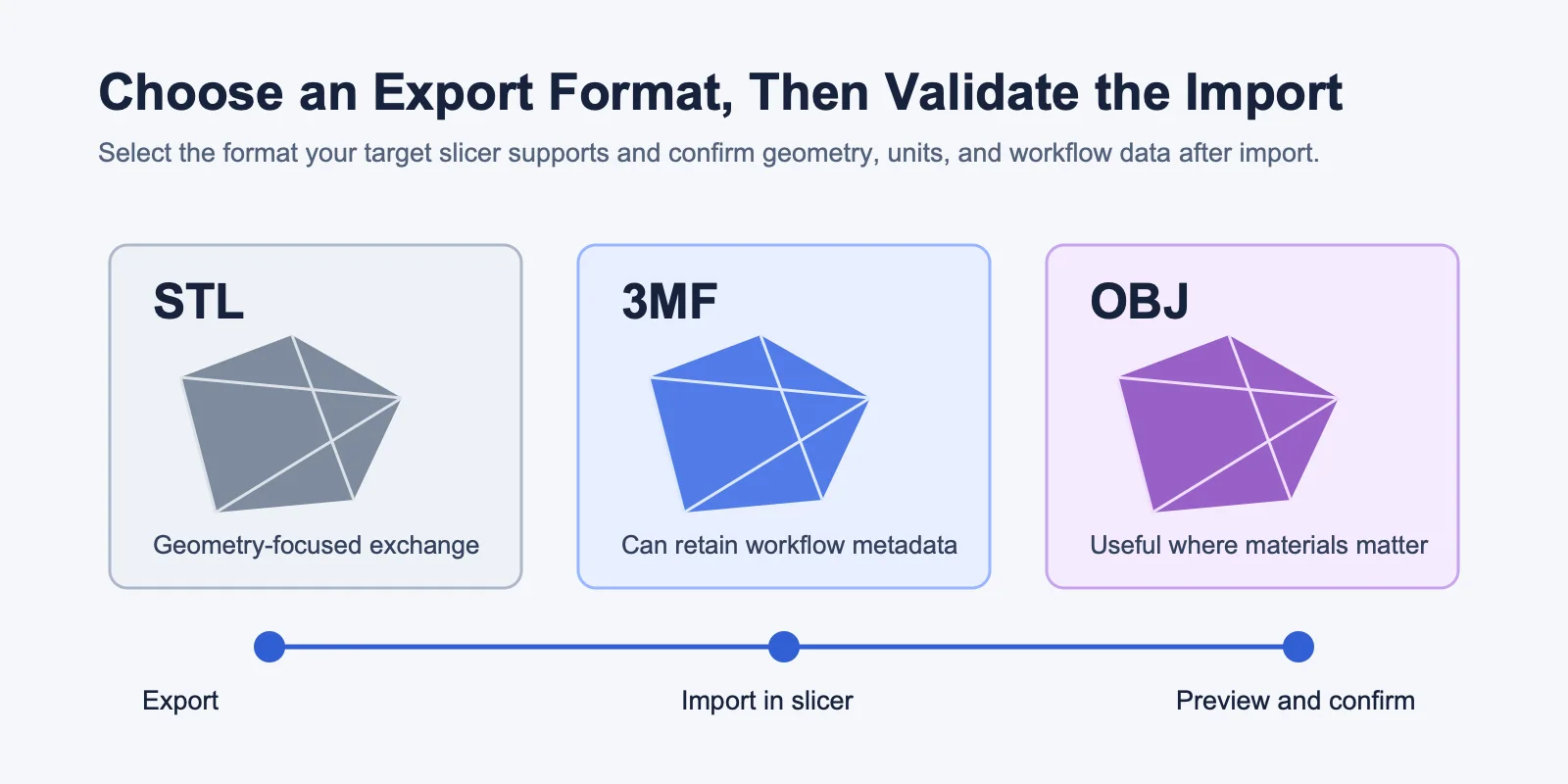
STL is the universal fallback supported by nearly every slicer. It stores triangulated geometry but not color, materials, print settings, or reliable unit metadata; binary STL is usually smaller than ASCII STL.
3MF is the better modern option when supported. It can store units, scale, color, multiple objects, materials, and print settings in one file.
OBJ can carry UV maps and materials, making it useful for color or multi-material workflows. For single-color FDM printing, it is usually less convenient than STL or 3MF.
Recommendation: use 3MF when supported, STL as the fallback, and OBJ only when you need materials, UVs, or color data.
Use File Repair Tools
Even careful models sometimes need repair. This is especially common with scanned models, imported assets, Boolean-heavy designs, or AI-generated objects that have been heavily edited.
Use these free or built-in tools before sending a file to the printer:
- Mesh-analysis feature: Locate non-manifold edges, holes, intersections, and internal faces in the modeling workflow.
- Automated mesh repair: Fill holes, correct normals, and remove duplicate or overlapping geometry, then inspect the output.
- Slicer import check: Review geometry warnings and repair prompts when the model is imported.
- Desktop repair utility: Open the exported file, run its available repair checks, and save a verified copy.
- Production-profile preview: Slice the repaired file and inspect the layer preview before sending it to the printer.
A simple repair workflow looks like this:
- Export the model from your design software.
- Open it in a mesh-repair tool or a modeling workflow with mesh-analysis features.
- Run automatic repair and inspect the fixed mesh.
- Re-export, then import into your slicer for final preview.
Do not skip this step if the slicer shows missing layers or strange geometry. Repair and recheck the file before committing material and machine time to the full print.
Run Slicer Checks Before You Print
The slicer is your final checkpoint before using filament, resin, or machine time. Even if the model looks correct in the design workflow, always slice and preview it with the target production profile.
Check these items before printing:
- Layer preview: Scroll layer by layer to catch missing walls, disconnected islands, voids, or thin sections that disappear.
- Infill and wall count: Start with the printer and material documentation for the intended part, then verify strength, weight, and surface quality with a test coupon.
- Support preview: Make sure supports reach the needed overhangs and can be removed without damaging the model.
- First layer: Confirm it has enough bed contact and is slightly squished for adhesion.
- Time and material estimate: Compare the estimate with the expected part size and profile. Investigate unexpected changes in scale, infill, supports, or layer settings.
Most slicers provide layer previews. You can also inspect a model in Tripo’s 3D Viewer before the final slicer stage, but final print validation belongs in the slicer.
Run this check every time, even for previously printed models, because slicer profiles, materials, nozzles, and support settings can change.
FDM vs Resin: Key Preparation Differences
FDM and resin printers both use 3D models, but they need different preparation choices.
| Prep Area | FDM Printing | Resin Printing |
|---|---|---|
| Wall continuity | Validate walls with the target nozzle, material, and production profile. | Validate walls for cleaning, curing, and the intended handling of the part. |
| Supports | Use previewed bridges, overhangs, and contact areas to decide where support is needed. | Inspect contact points and peel-sensitive areas, then test when detail or finish is critical. |
| Orientation | Balance layer direction, surface finish, stability, and support access. | Balance support access, drainage paths, surface finish, and forces shown in the slicer preview. |
| Material use | Validate infill and wall settings against the required strength and print time. | Validate hollowing and drainage against printer and material safety guidance. |
| Export and import | Confirm the file imports at the intended scale and slices without geometry errors. | Confirm the file imports correctly and the selected workflow preserves the intended geometry. |
For FDM model preparation, think about layer strength, overhangs, infill, and bed contact. For resin, think about suction forces, support marks, hollowing, drainage, and post-processing. The same STL may need a very different orientation depending on which printer type you use.
Hollowing Models to Save Material
Hollowing is most useful for large resin prints and decorative objects where a solid model would use unnecessary material. Use the hollowing tools in the target resin workflow, but validate the result before printing.
For resin, follow the printer and material manufacturer guidance for hollowing and drainage. Ensure the model has drainage paths that can clear uncured material, then validate the result with a small sample before a full print. Trapped resin can leak, crack the model, or cause curing problems.
For FDM, true hollowing is often less important. Adjust infill and wall settings for the required strength, print time, and material use, then validate the result with the selected production profile.
Frequently Asked Questions
How do I prepare a 3D model for printing?
Check wall thickness, make the mesh watertight, set the correct scale, orient the model, add supports, and export as STL or 3MF. Always run a slicer preview before printing.
What is the first step in preparing a 3D model for printing?
Start with wall thickness and mesh integrity. Thin walls or non-manifold geometry can fail even if orientation and supports are correct.
What does it mean for a 3D model to be manifold?
A manifold model is a closed solid where every edge is shared by exactly two faces. Slicers need this to calculate walls, infill, inside, outside, and print volume.
How do I start making 3D models for printing?
Choose a workflow based on your goal: a beginner-friendly browser workflow for simple concepts, a sculpting or mesh workflow for organic shapes, a parametric CAD workflow for precise parts, or Tripo AI for a fast AI-generated base mesh. Build with printability checks from the start.
Can AI-generated models be used for 3D printing?
AI 3D tools such as Tripo AI can generate a 3D starting mesh from text or images. Inspect and prepare the mesh for the target printer, material, and slicer profile before printing.
How do I fix a non-manifold or broken 3D model?
Open the file in a mesh-repair tool or modeling workflow with repair checks. Use it to fill holes, correct normals, remove broken geometry, inspect the output, and re-export before the final slicer preview.
What is the best file format for 3D printing?
Use 3MF when your slicer supports it because it preserves units, scale, multiple objects, and print data. STL is the universal fallback for nearly every slicer.
Conclusion
Before printing, make sure your model passes the four essential checks:
- Wall thickness: strong enough for your printer type.
- Watertight mesh: no holes, non-manifold edges, or broken geometry.
- Orientation and supports: stable, strong, and easy to clean up.
- Slicer preview: no missing layers, wrong scale, or unexpected print time.
Careful preparation eliminates many print failures before they start. A print-ready model is not just one that looks good on screen; it must be solid, scaled correctly, exportable, and verified in the slicer.
Ready to model? Try Tripo AI Studio to generate a 3D starting mesh from text or an image, then complete the print-preparation checks in this guide.
Explore Tripo AI Pricing to find the plan that fits your workflow.