A Studio Workflow Case Study — From Concept Art to Game Engine in One Day
1. Project Snapshot
| Project Snapshot | Details |
|---|---|
| Subject | Full game-ready character pipeline, concept art -> Unreal Engine |
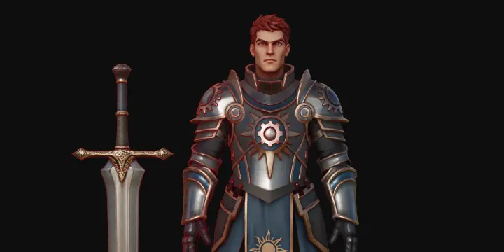
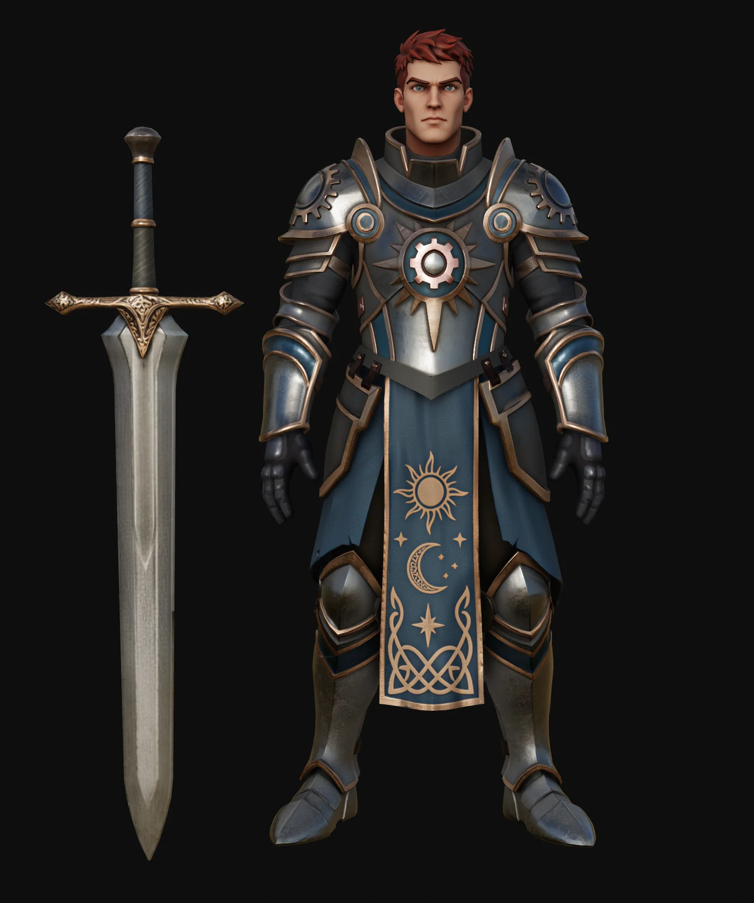
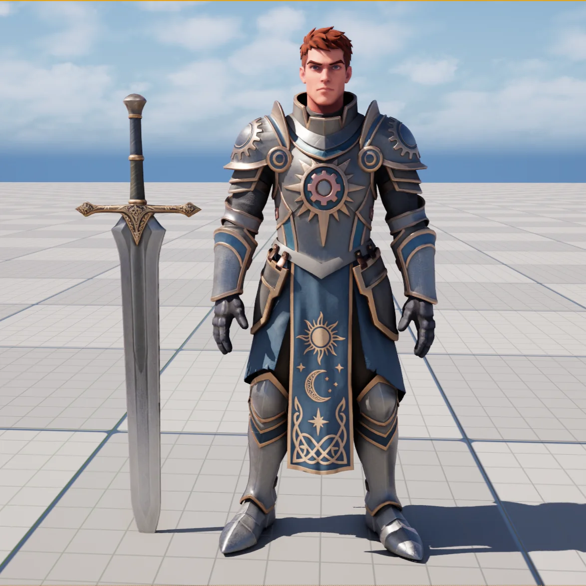
| Showcase Asset | Stylized knight, modular armor set |
| Total Turnaround | 1 working day, single artist |
| Traditional Baseline | Several days to several weeks, multiple specialists in parallel |
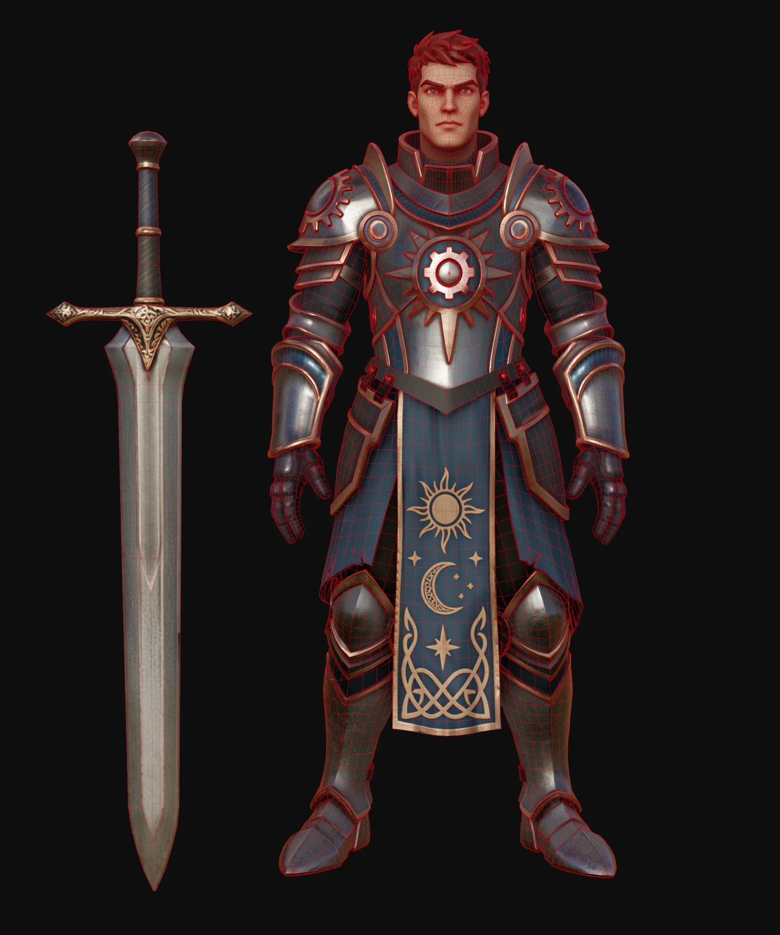
| Final Budget | Under 30K triangles total, quad-based topology |
| Tripo Modules Used | Image Generation (Asset Extraction, Head Extraction, 3D Enhance) · Smart Mesh P2.0 (Quad) · Texture Generation (4K / 8K) · Texture Edit · PBR Processing · DCC Bridge |
| DCC Stack | Maya (assembly, UV) · Marmoset (bake) · Substance Painter (refinement) · Unreal Engine (integration) |
| Core Value | Compresses the concept-to-textured-asset span so senior artists spend their hours on artistic refinement instead of repetitive block-out and base texturing |
| Credits Usage | 600+ |
Positioning statement. Tripo does not replace the character artist. It removes the mechanical middle of the pipeline — the base mesh, the clean edge flow, the first-pass texture set — and hands the artist back the hours that matter.
2. The Challenge
Traditional character production is a long serial chain, and every link may demands a specialist.
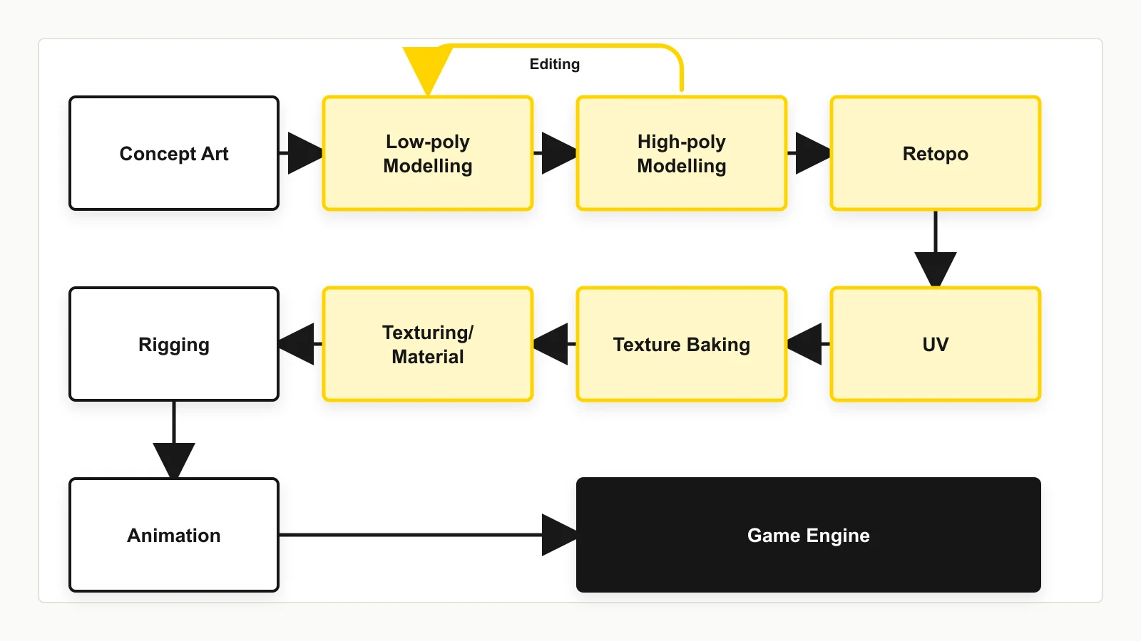
Concept Art → Blockout → High-Poly Sculpt → Retopology → UV →
Bake → Texturing → Material Setup → Rig → Engine Integration
Three structural problems follow from this shape:
Cost is front-loaded onto the least creative work. Sculpting a base form and retopologizing it consume a disproportionate share of the schedule, yet neither is where artistic value is created. They are prerequisites, not contributions.
Serial dependency blocks iteration. Because texturing waits on UVs, and UVs wait on retopology, a late-stage art direction note on silhouette or material can invalidate several days of downstream work. Teams learn to resist changes rather than explore.
Headcount is the only scaling lever. Compressing the schedule conventionally means adding specialists — concept, high-poly, texture — which raises coordination cost and makes small teams structurally unable to compete on asset volume.
The question this case study answers: for a professional artist who already knows how to do all of this, where does an AI 3D generation tool actually pay off?
3. Technical Solution
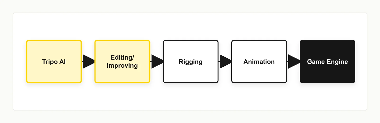
3.1 The Revised Pipeline
Tripo collapses the block-out, high-poly, retopology, and base-texturing stages into a single generation pass, leaving human effort concentrated at the two ends — art direction at the front, refinement and technical finish at the back.
3.2 Design Principles Behind the Workflow
Component-wise generation over monolithic generation. A single-image, single-mesh generation is fast and adequate for props. For a character with distinct material zones and varying detail requirements, separating the concept into components before generation yields materially better results — each part gets its own polygon budget, its own texture, and its own iteration loop.
Reference image quality determines output quality. The generated mesh and texture inherit whatever geometric and material information the reference image carries. Investing in the reference — clear silhouette, readable details, PBR-like material cues — is the highest-leverage step in the entire pipeline.
Quad topology as the integration contract. Triangulated output is a dead end for an artist; it cannot be edited, symmetrized, or re-UV'd efficiently. Quad output with industry-standard edge flow is what makes the handoff from AI to DCC viable, and it is the foundation everything in Phase C depends on.
Phase A · Concept & Reference
Step 1 — Prepare Concept Art
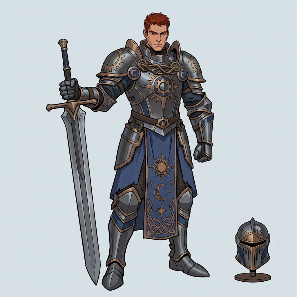
Concept art may be artist-authored or AI-generated; the pipeline is agnostic. What matters is legibility to the generation model.
Best Practice
- Clear, readable silhouette
- Avoid heavy shadow areas that occlude form
- Avoid ambiguous or unresolved detail
Step 2 — Part Separation
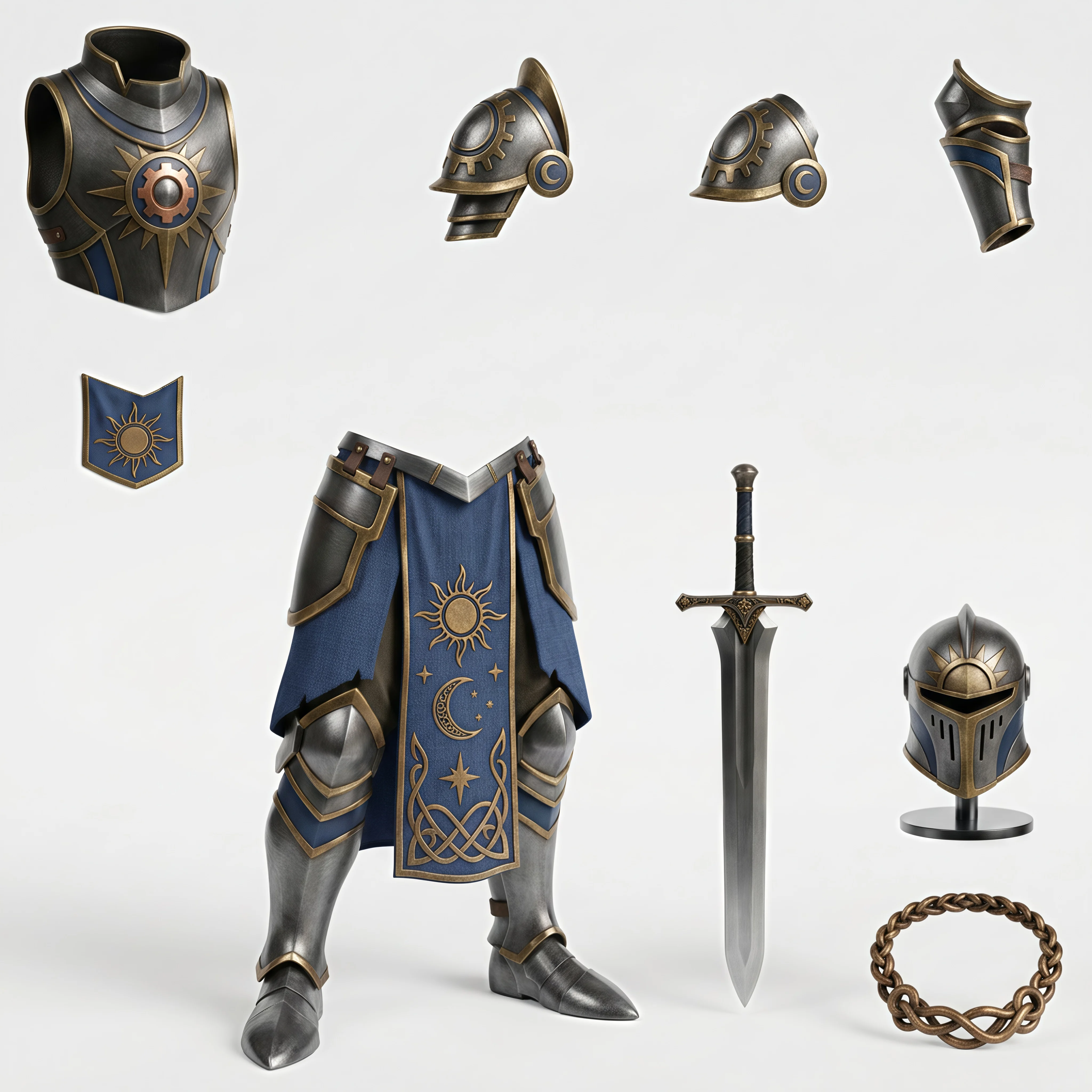
Simple characters and props can go straight to generation from a single image. For maximum quality, separate the concept into components first.
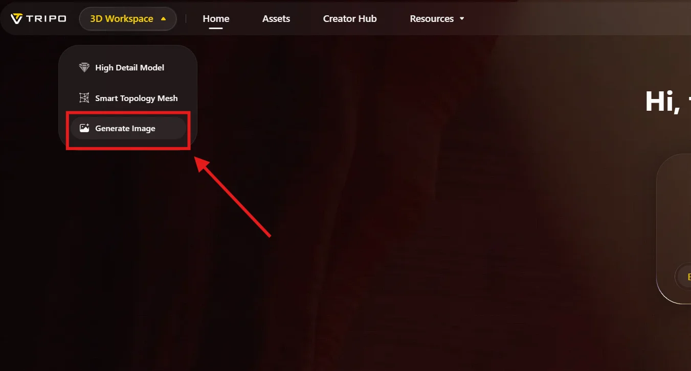
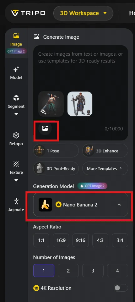
Log in at tripo3d.ai and hover to the top left, choose Generate Image first.
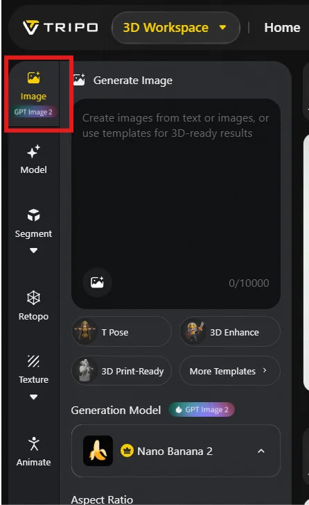
From the workspace, open the Image panel in the upper-left corner. This is where concept art is created or edited.
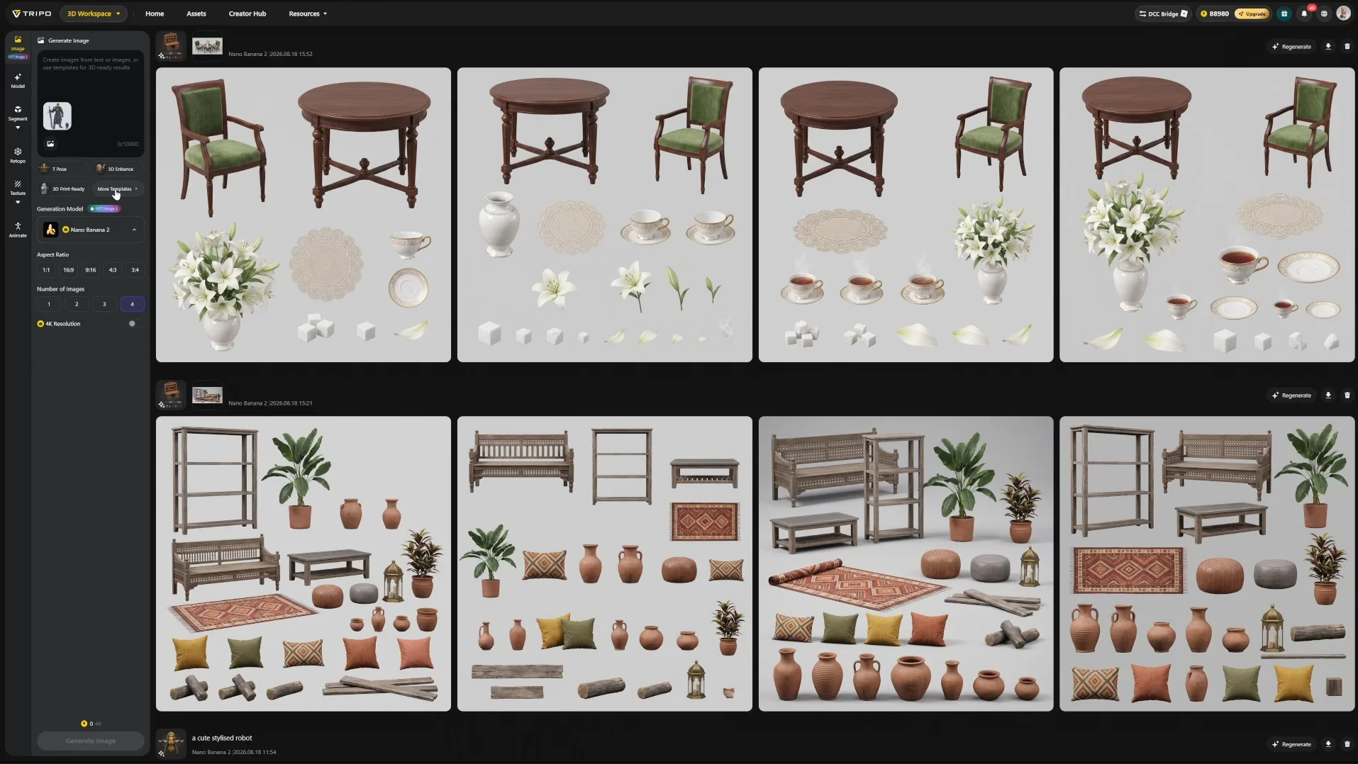
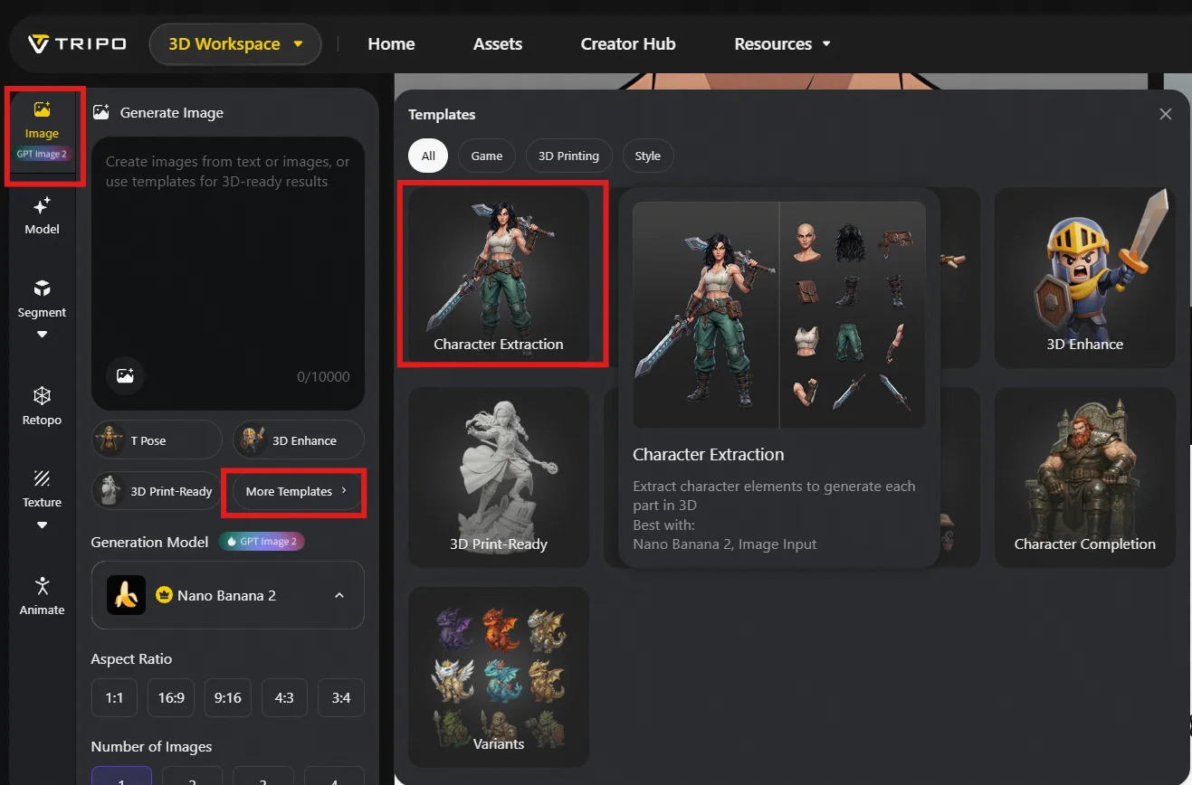
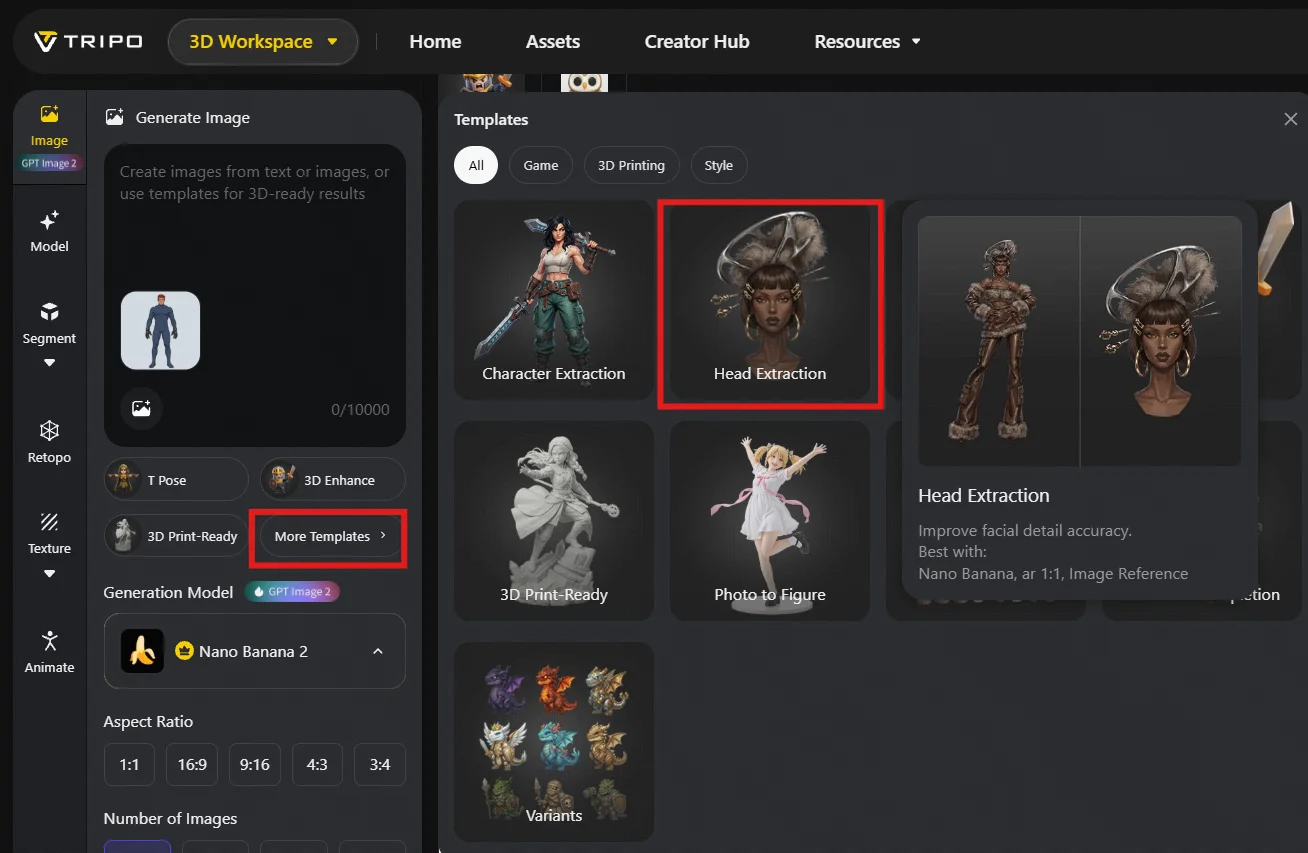
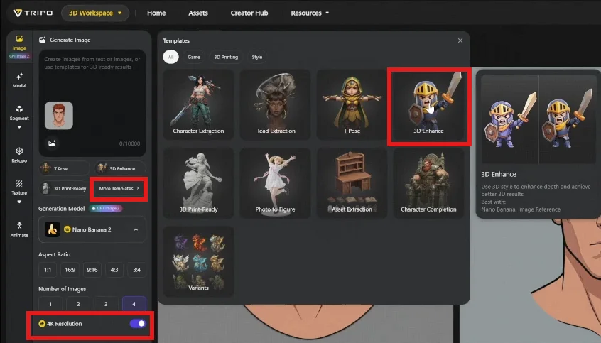
Navigate to More Templates → Character Extraction.
Upload the concept art. Settings can be tuned as needed; defaults are sufficient for most cases.
You can choose your generation model, currently the best image editing generation model is Nano Banana Pro.
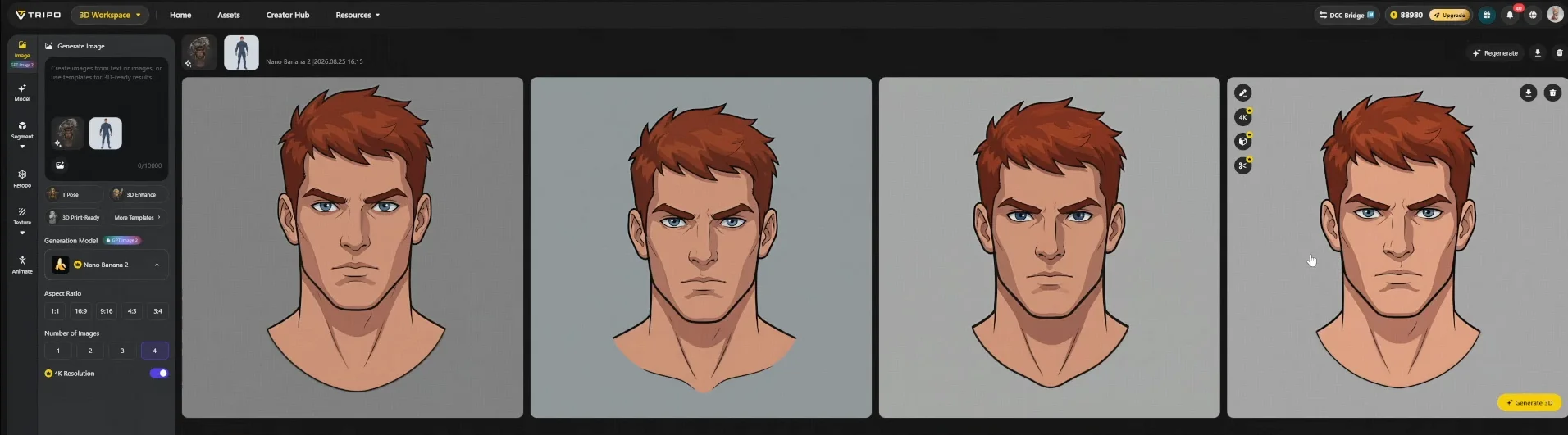
Generate returns four candidates.
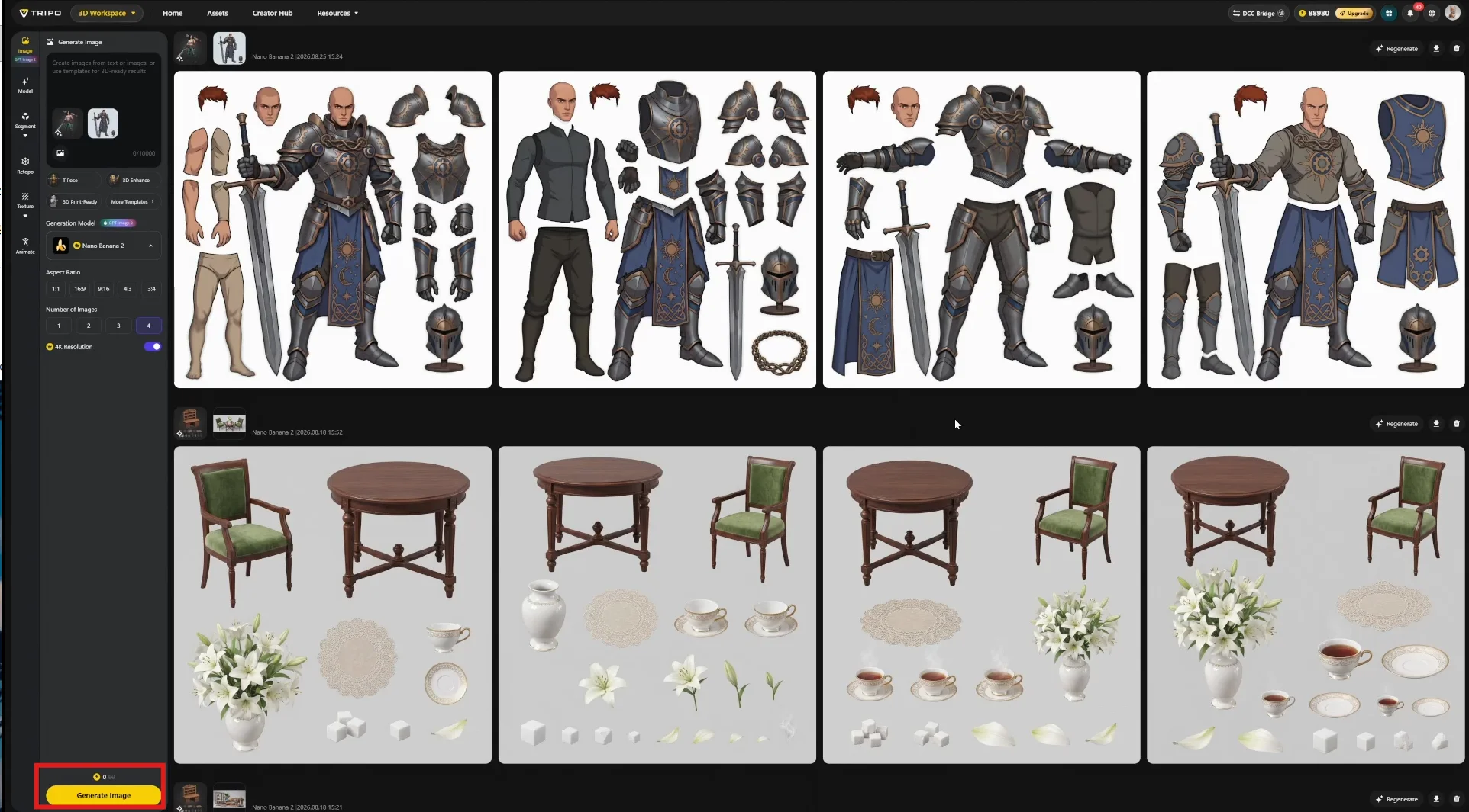
Select the result that contains every component you intend to build. Regenerate if none qualifies — this selection dictates the entire downstream part list.
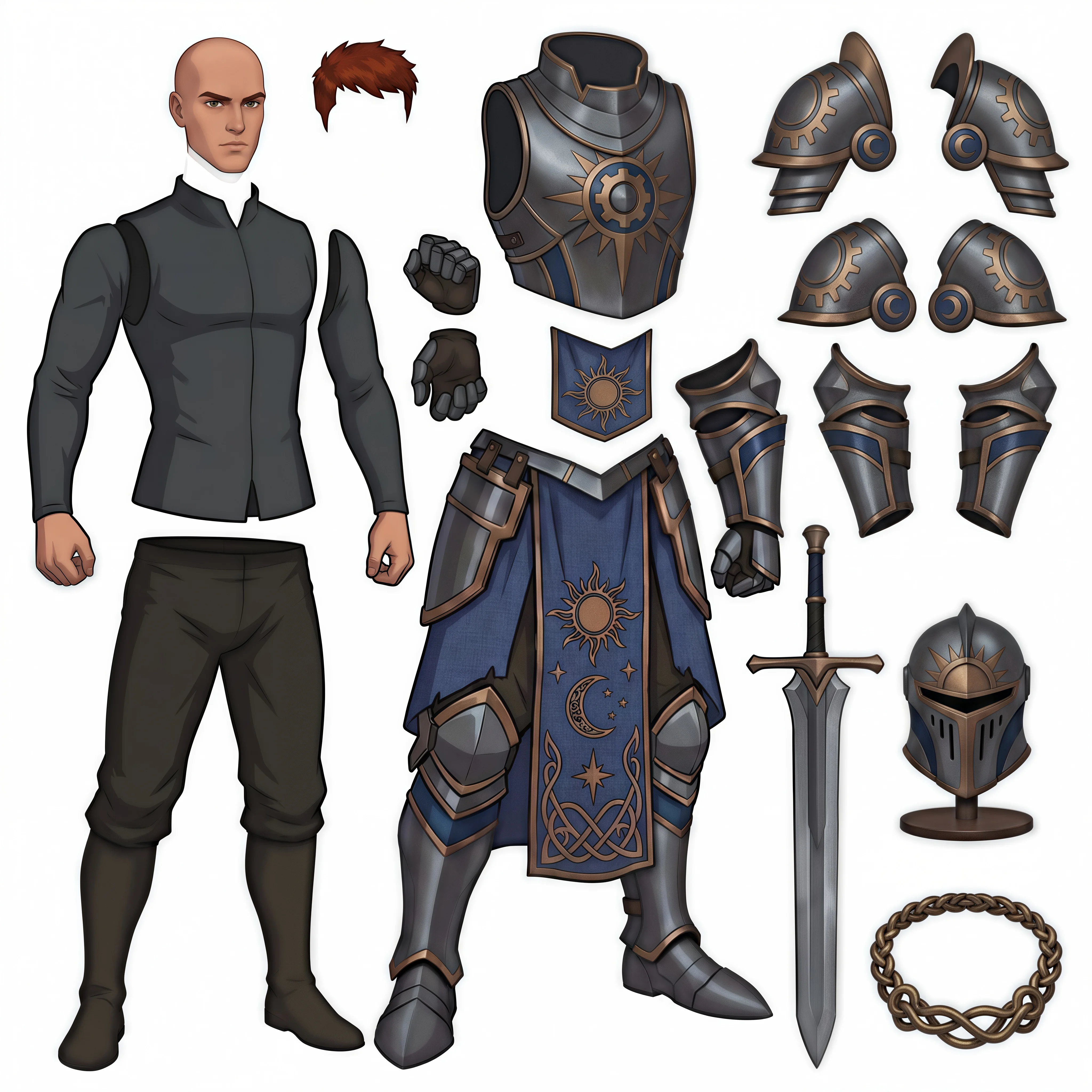
Step 3 — Hero Part Isolation
Not every component should be treated equally. Two cases warrant separate generation passes.
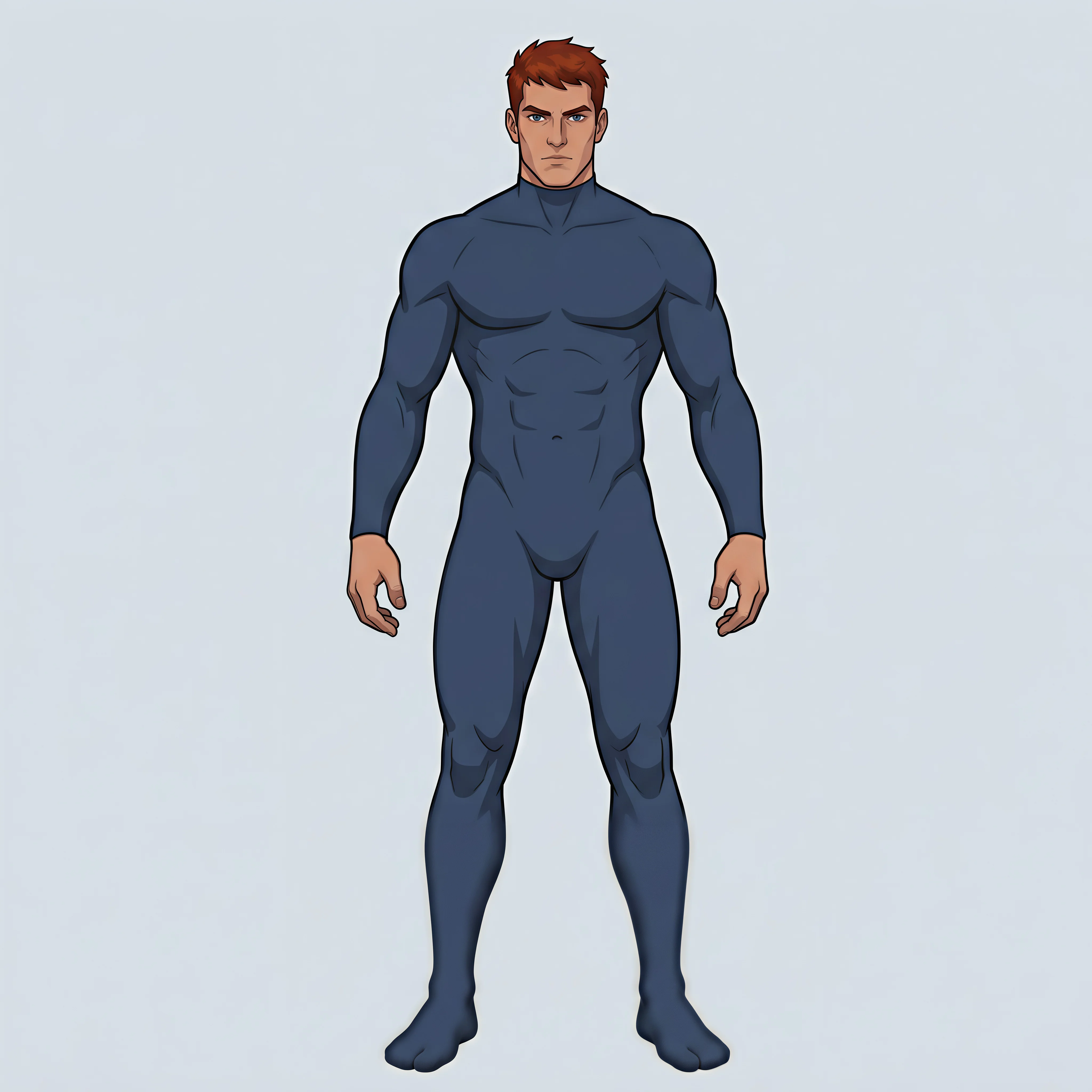
Full body as a single piece. If the automatic separation fragments the body in an unhelpful way, prompt the left panel to generate the body alone.
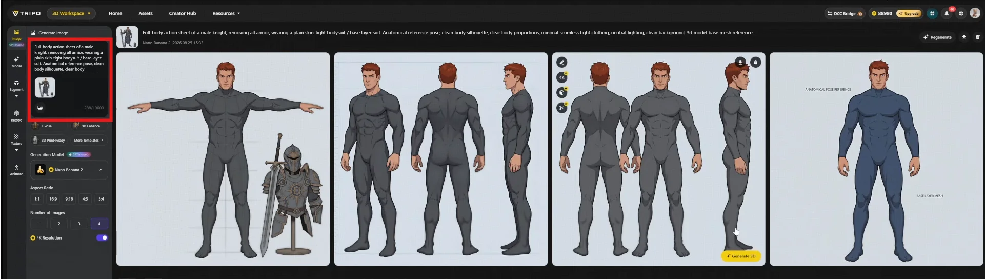
For this showcase the selected reference has a clear front view in A-pose, which suits armor placement. T-pose is the better choice if rigging setup is the priority — worth deciding before generation, not after.
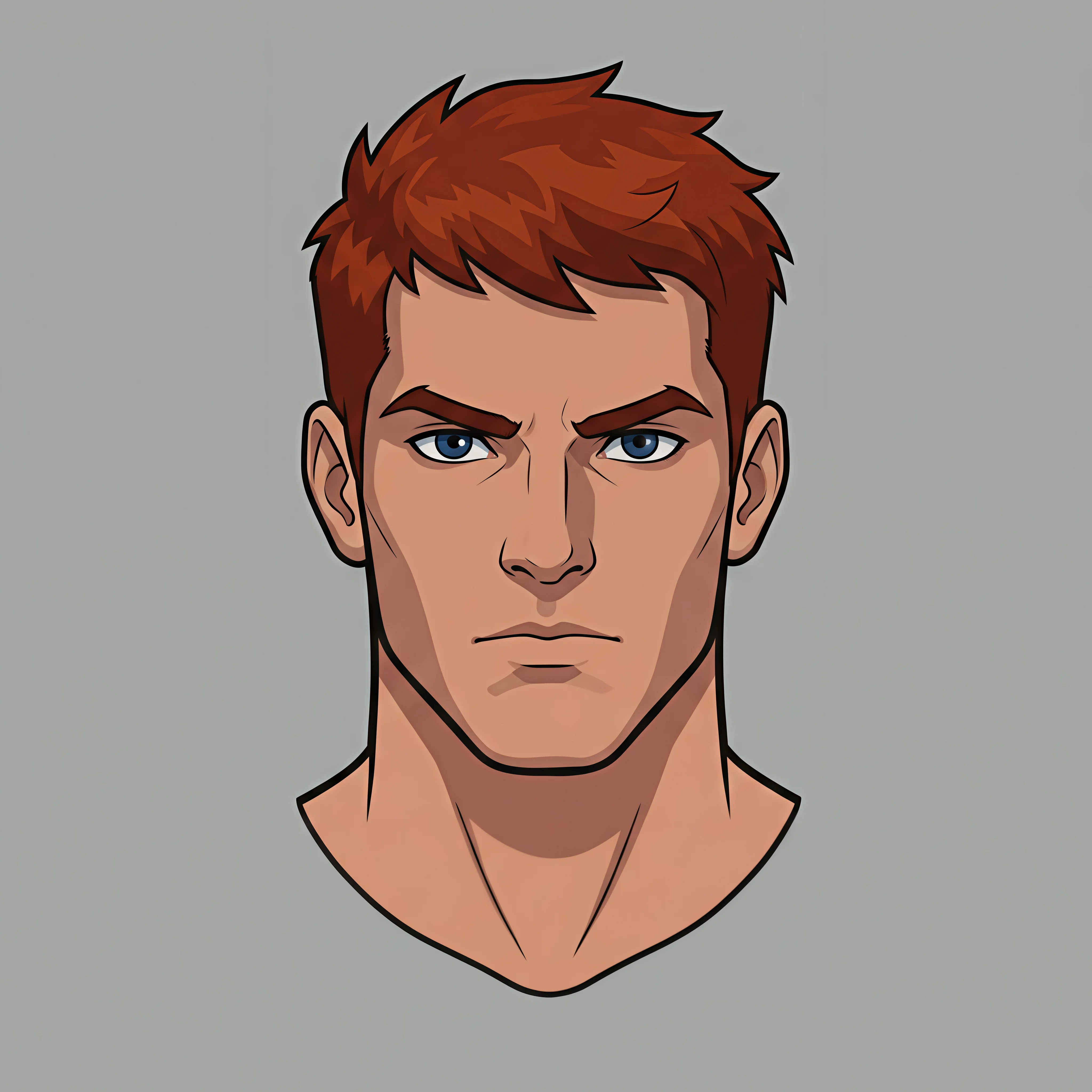
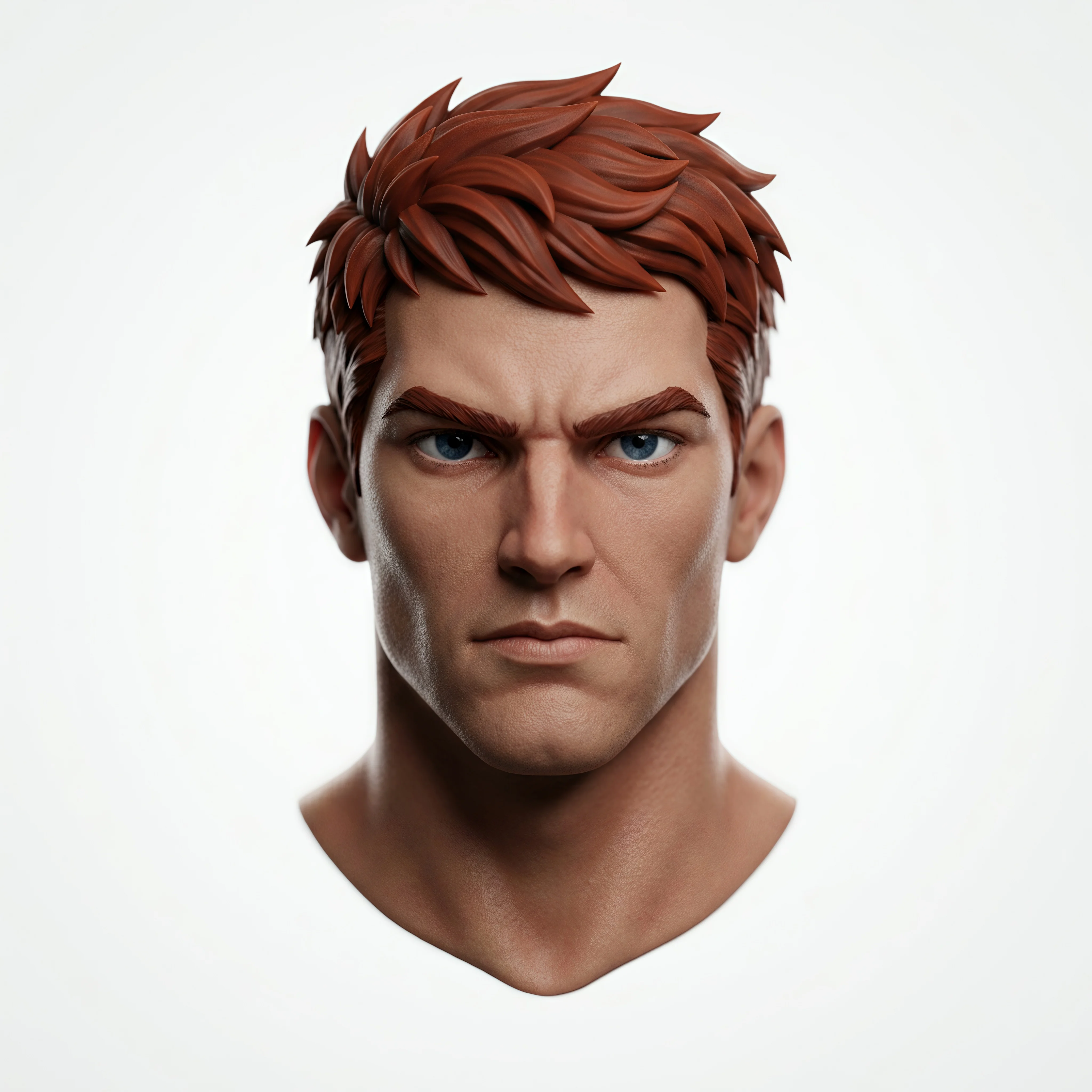
Head as a dedicated asset. The head carries the most viewer attention and therefore deserves a larger share of the polygon and texture budget than any other part. Use the Head Extraction template to isolate it.
Step 4 — Reference Refinement
Before generation, bring each reference closer to the intended final look. The goal is to maximize the geometric and material information available to the model.
A PBR-style treatment is the general-purpose recommendation, applied here via the 3D Enhance template. Adjust to match your project's art direction — the reference should look like what you want the output to be.
Phase B · Generation in Tripo
Step 5 — Mesh Generation
3D models can be directly generated from the Image workspace.
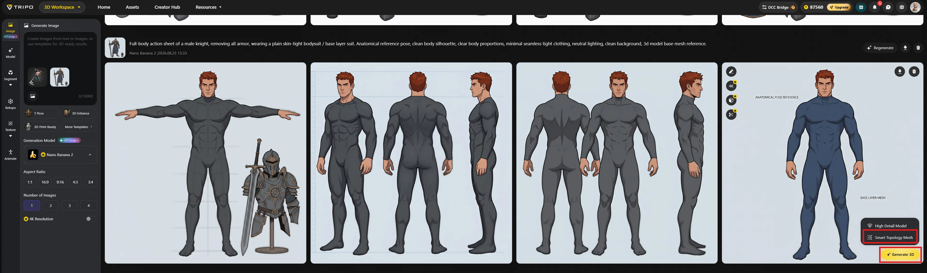
Alternatively, Navigate Model → Smart Mesh → upload the refined reference.
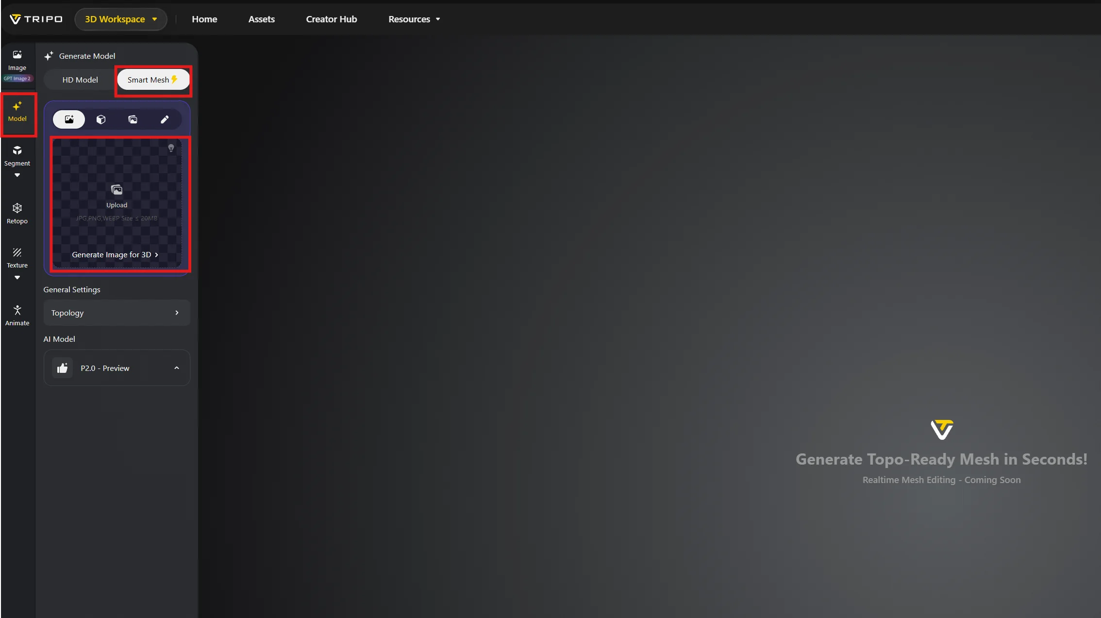
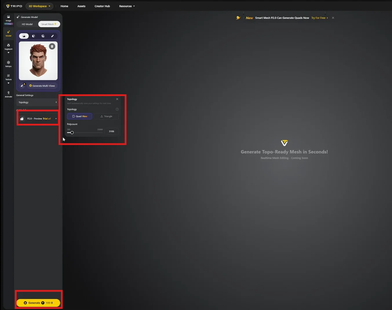
Under Topology, select Quad and set the polygon budget. This showcase uses 3,000 polygons for the head, targeting a sub-30K total for the assembled character.
P2.0 is the current generation model, producing industry-standard edge flow.
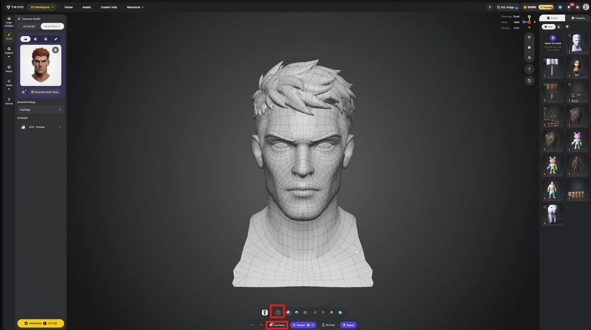
Generation completes in under one minute. Verify edge flow using the wireframe toggle at the bottom of the viewport. Retries are available at no cost if the result is not usable.
In practice the mesh arrives over 90% production-ready, with only minor localized issues where topology falls short of ideal.
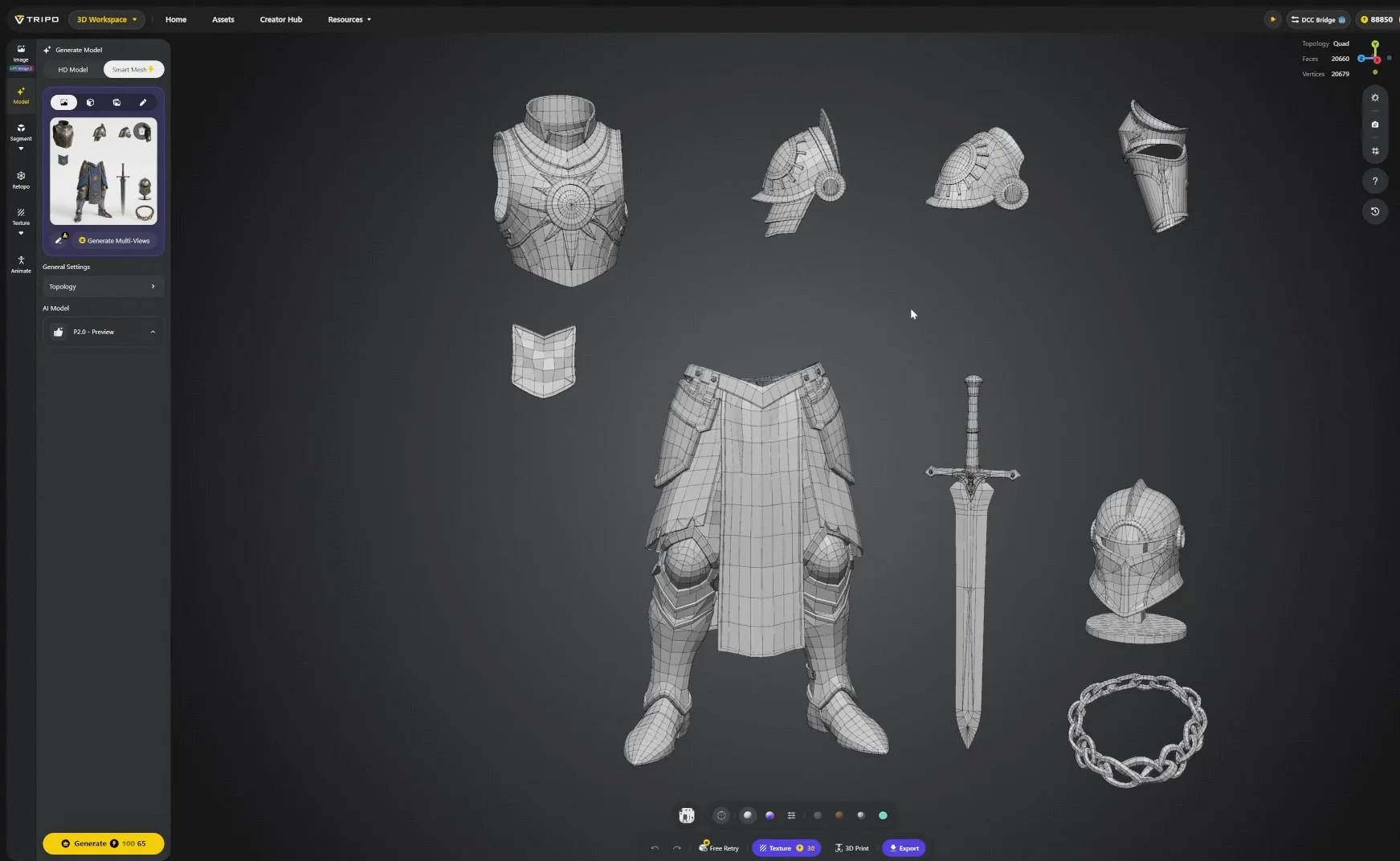
Batch Strategy: Cost vs. Quality
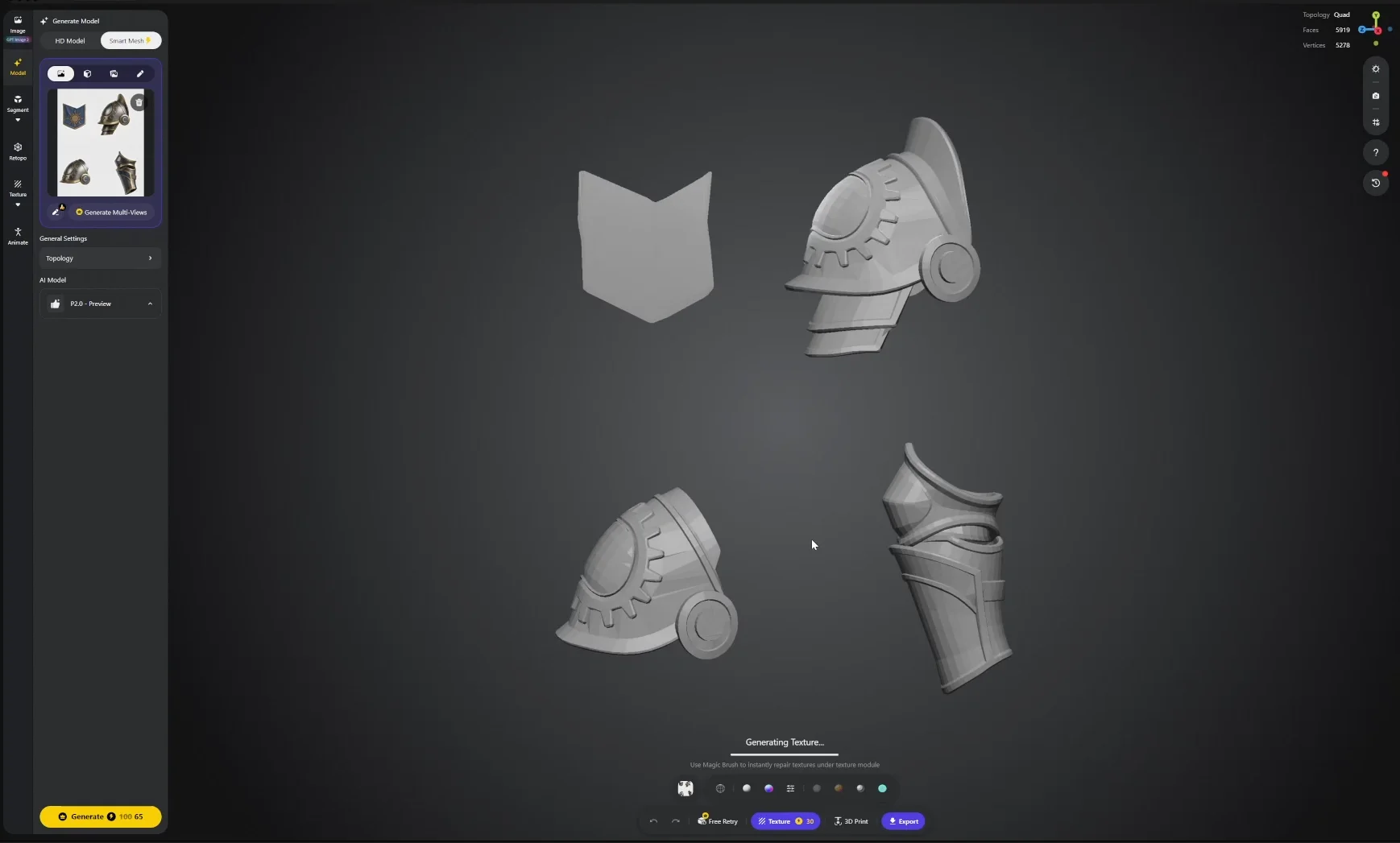
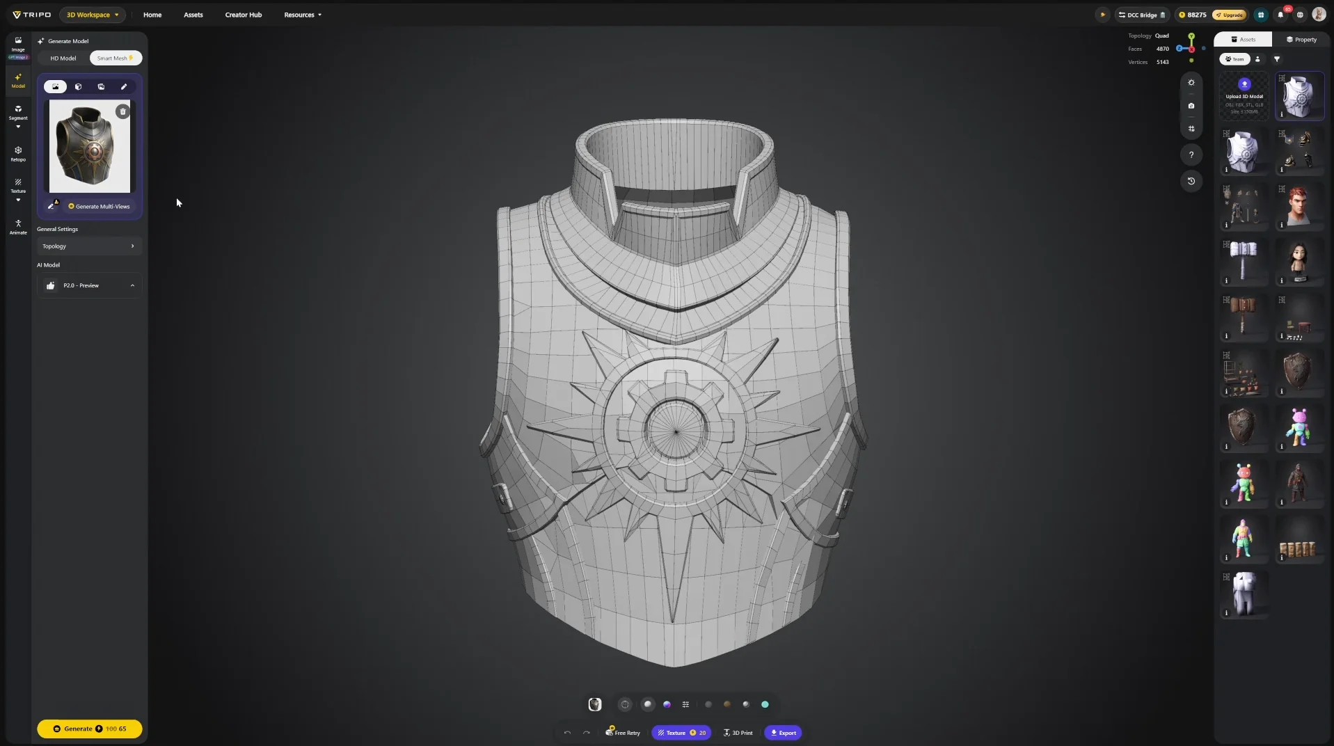
Step 6 — Texture Generation
Textures can be generated from the lower toolbar, or from the left panel for expanded options. Generation takes a few minutes.
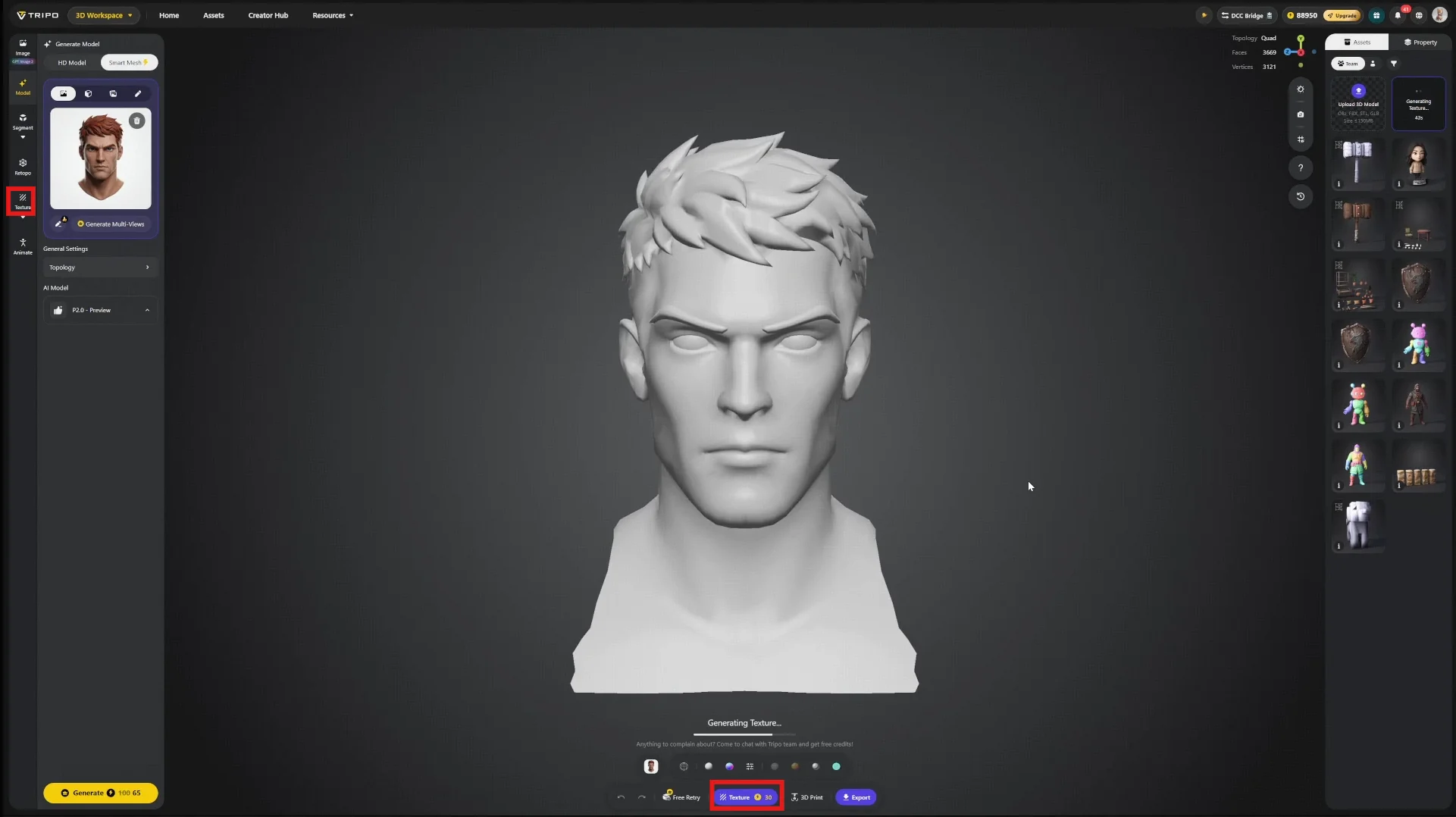
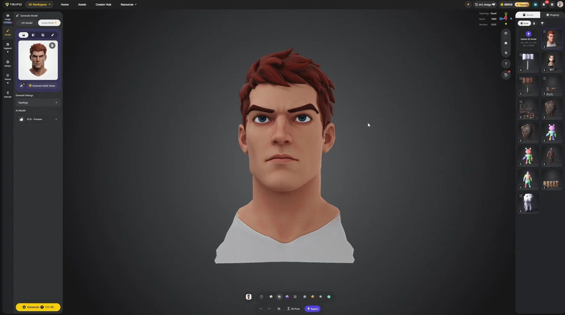
For this showcase an 8K pass was also generated from the left panel. 8K is not a shipping resolution in games, and it is not used directly here — it serves as source material for the refinement stage in Step 13, where the extra headroom matters.
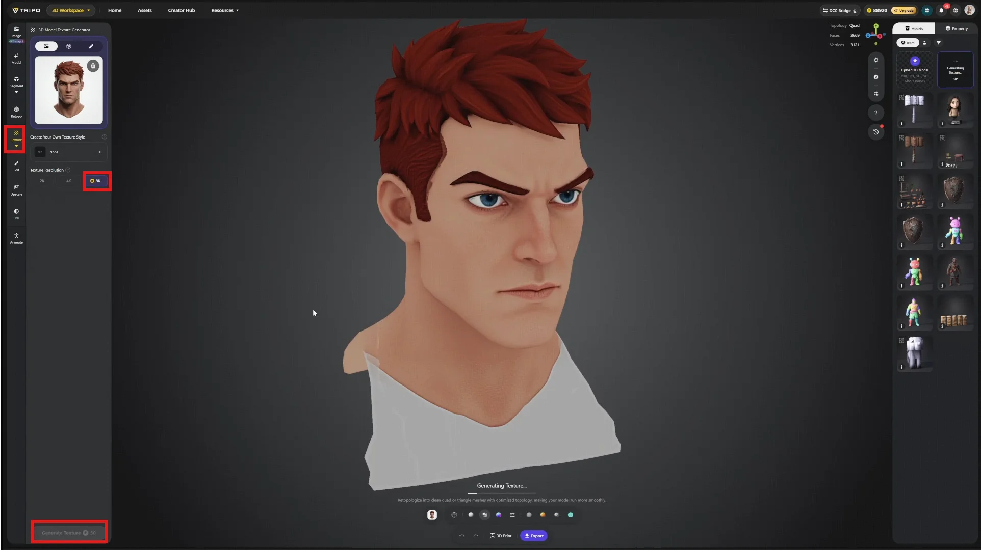
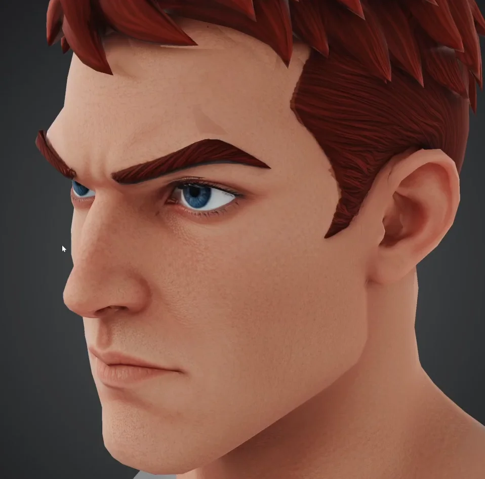
8K texture provides you with the best quality out of the box.
Step 7 — Texture Editing
Generated textures are not always perfect in the first pass. The Edit tool, located beneath the texture options, handles localized correction.
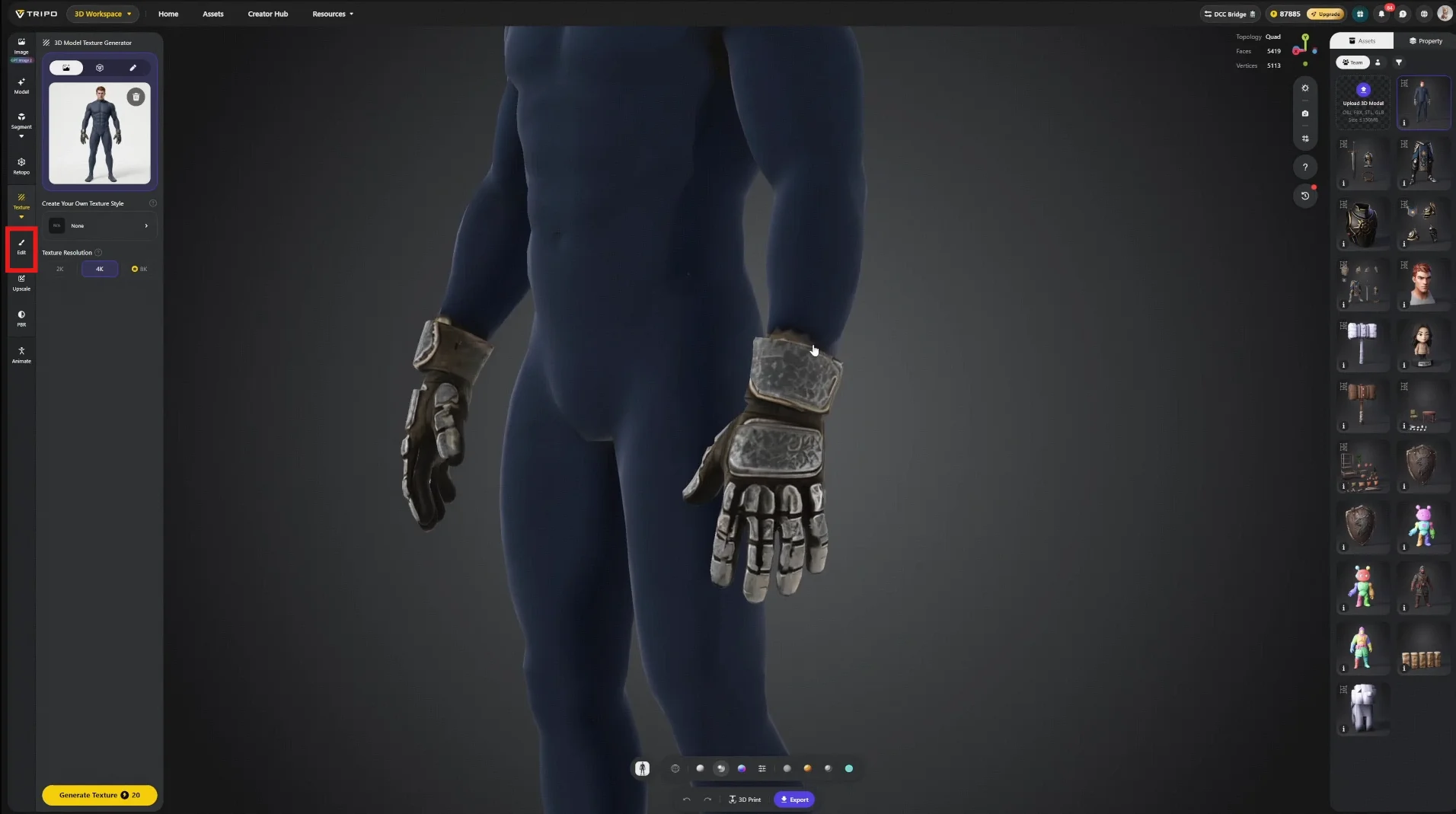
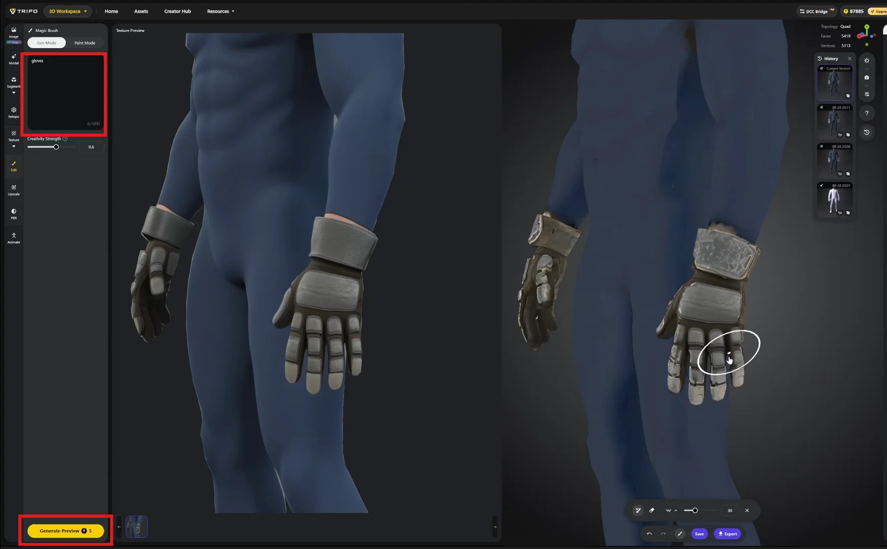
Describe the area to repaint, then Generate Preview. The result appears as a projection overlay in the left panel, and paints onto the model exactly like a conventional projection paint workflow.
Important — Scope of the Edit Tool
Edits apply only to the current viewing angle. Painting from the front does not update the back faces. Treat this as targeted repair, not full-surface repainting.
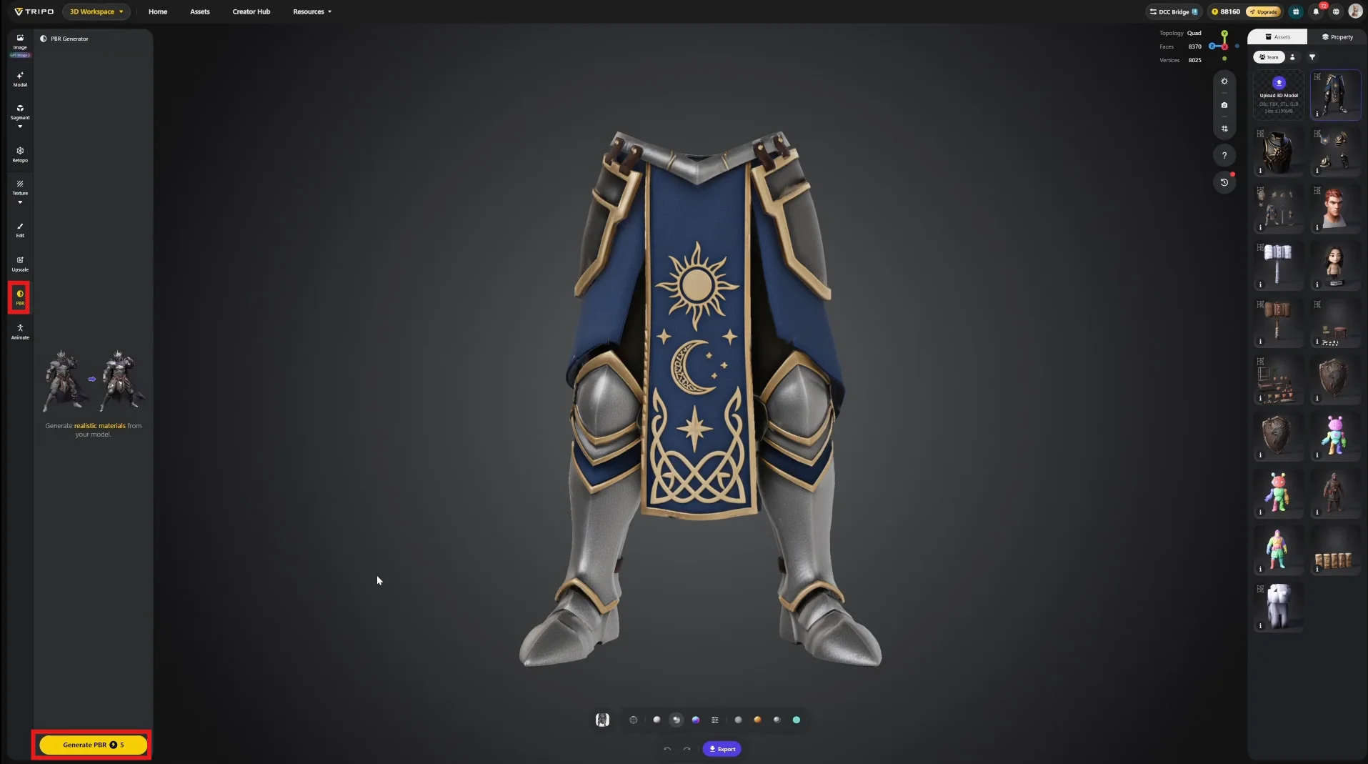
Step 8 — PBR Processing
Convert the single base color output into a complete texture set — normal, roughness, metalness — via the PBR function in the left panel.
Step 9 — Export
The DCC Bridge sends the asset directly into your modelling software, skipping the file round-trip.
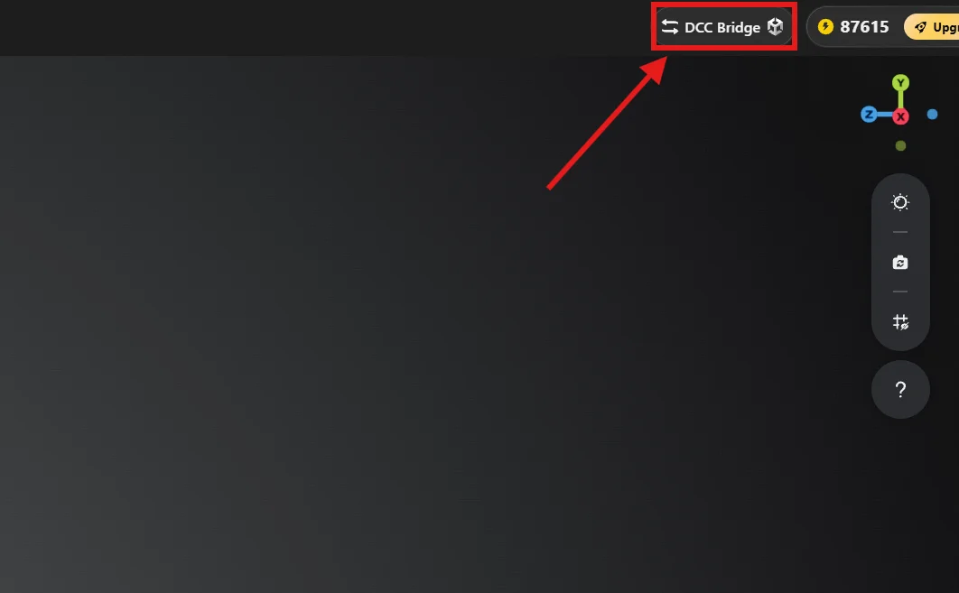
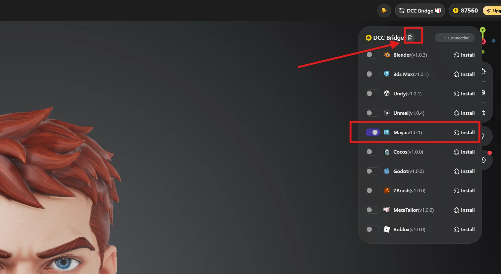
Make sure you install the DCC Bridge plugin correctly, the installation guide can be found by clicking the document icon.
Turn on the plugin to auto sync, the Tripo web page and your target engine or platform must be open simultaneously. Transfers will fail if the receiving application is closed.
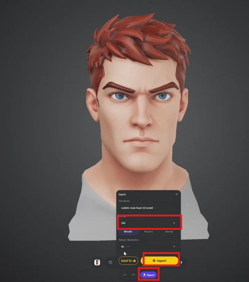
Alternatively, export in your working format; FBX and OBJ are the common choices.
Phase C · Production Finish
This phase is where the artist's expertise re-enters. Tripo has delivered geometry and textures; converting them into a shippable high-quality game asset remains craft work.
Step 10 — Re-assembly
Tripo normalizes all models to a uniform scale, which is not what you want when components must differ in size. Assembly happens in your DCC of choice — Maya, Blender, 3ds Max, ZBrush, or 3D Coat.
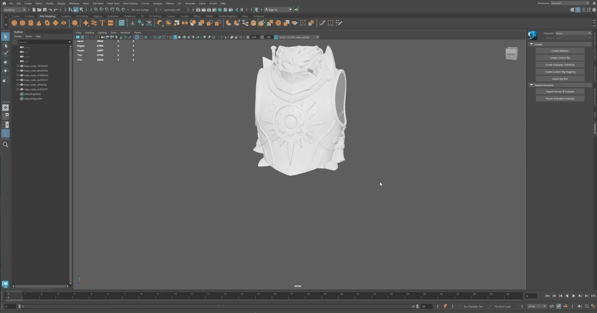
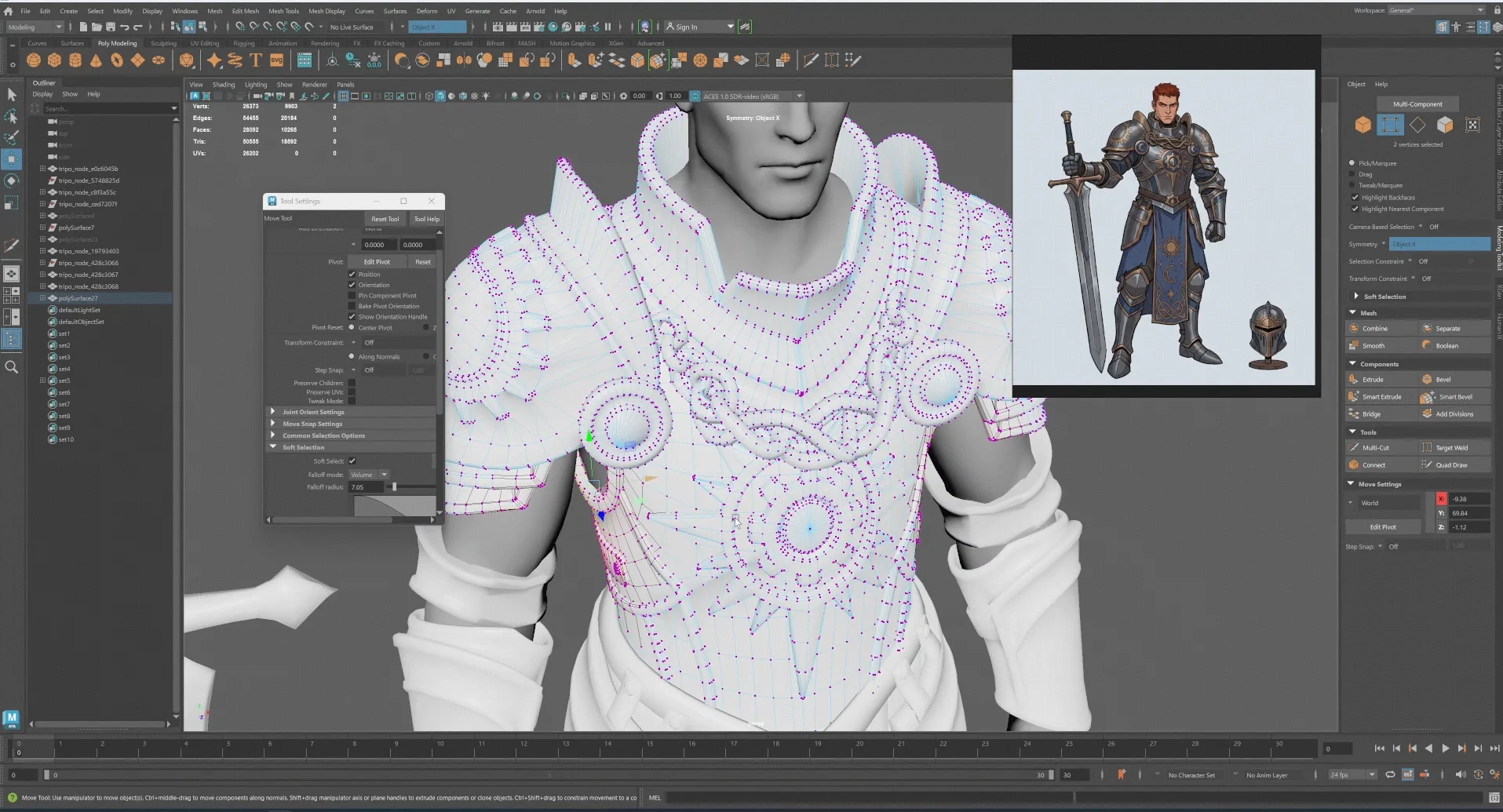
Maya is used here. Load the reference image and reconstruct the character from its components, holding symmetry and proportion as the governing constraints.
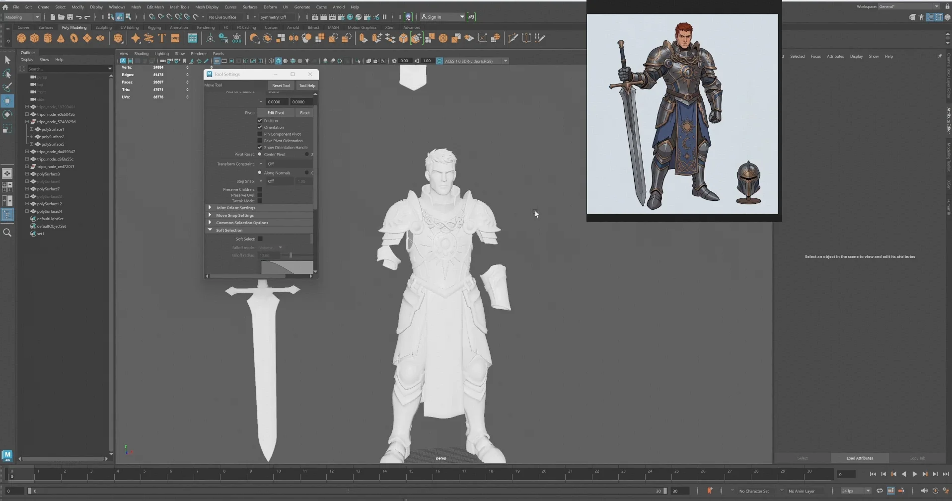
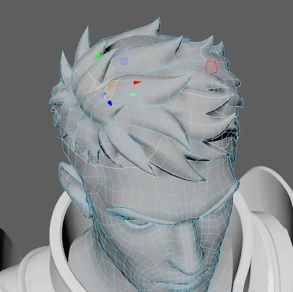
Some parts need manual adjustment. Move and scale to match the reference.
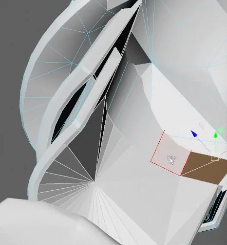
Non-manifold faces or holes may appear and currently require manual repair. Volume is low, and ongoing model updates continue to reduce it.
Step 11 — UV and Symmetry
Tripo provides symmetry functions, but verify the result against your own standard before proceeding.
Critical — Preserve Your Texture Mapping First
The Tripo-generated textures are bound to the original UVs. Duplicate the model before touching UVs. Losing the original UV set means losing the generated textures, and there is no recovery path short of regenerating.
The approach used here: delete one half of the body, build UVs on the remaining half, then mirror — producing both a cleaner UV layout and exact symmetry.
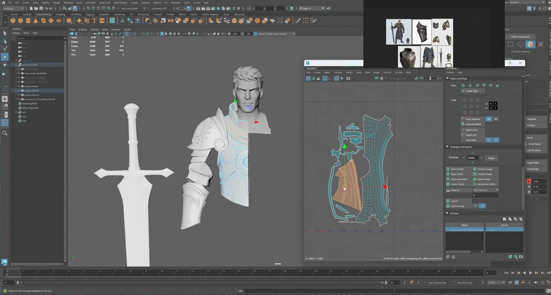
Repeat across all components until topology and UVs are both clean.
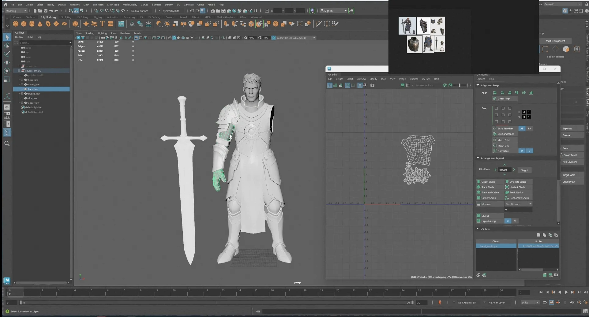
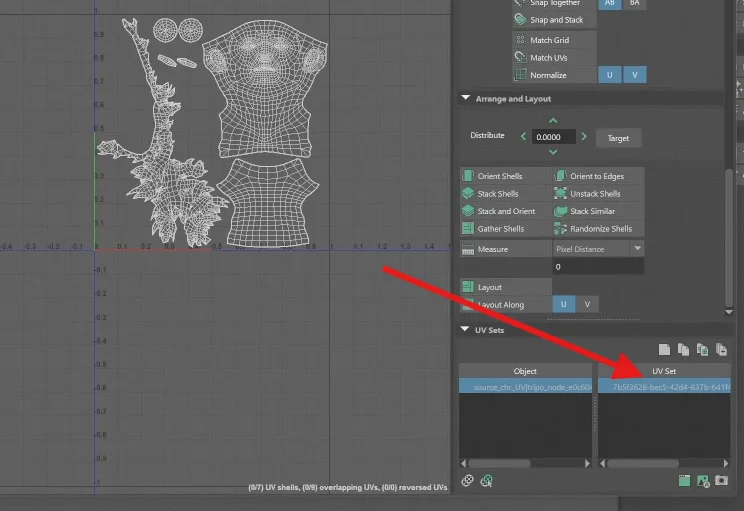
Critical — UV Set Naming
Rename all UV sets to a single consistent name rather than leaving defaults in place. Default UV set names differ between objects and will cause merge failures downstream. This is a cheap fix now and an expensive one later.
Step 12 — Texture Transfer and Baking
Transfer the Tripo textures onto the re-UV'd model. Either use world-space texture transfer in Maya, or bake with Marmoset or any comparable baking tool — the process is identical to a standard normal map bake, with the old model as the source.
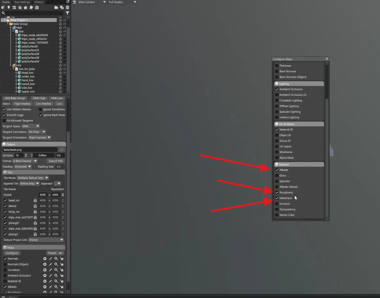
Step 13 — Refinement
With clean UVs and transferred textures in place, the final art pass begins. Substance Painter is used here, drawing on the 8K source generated in Step 6 and we can reduce it to 4K or 2K now.
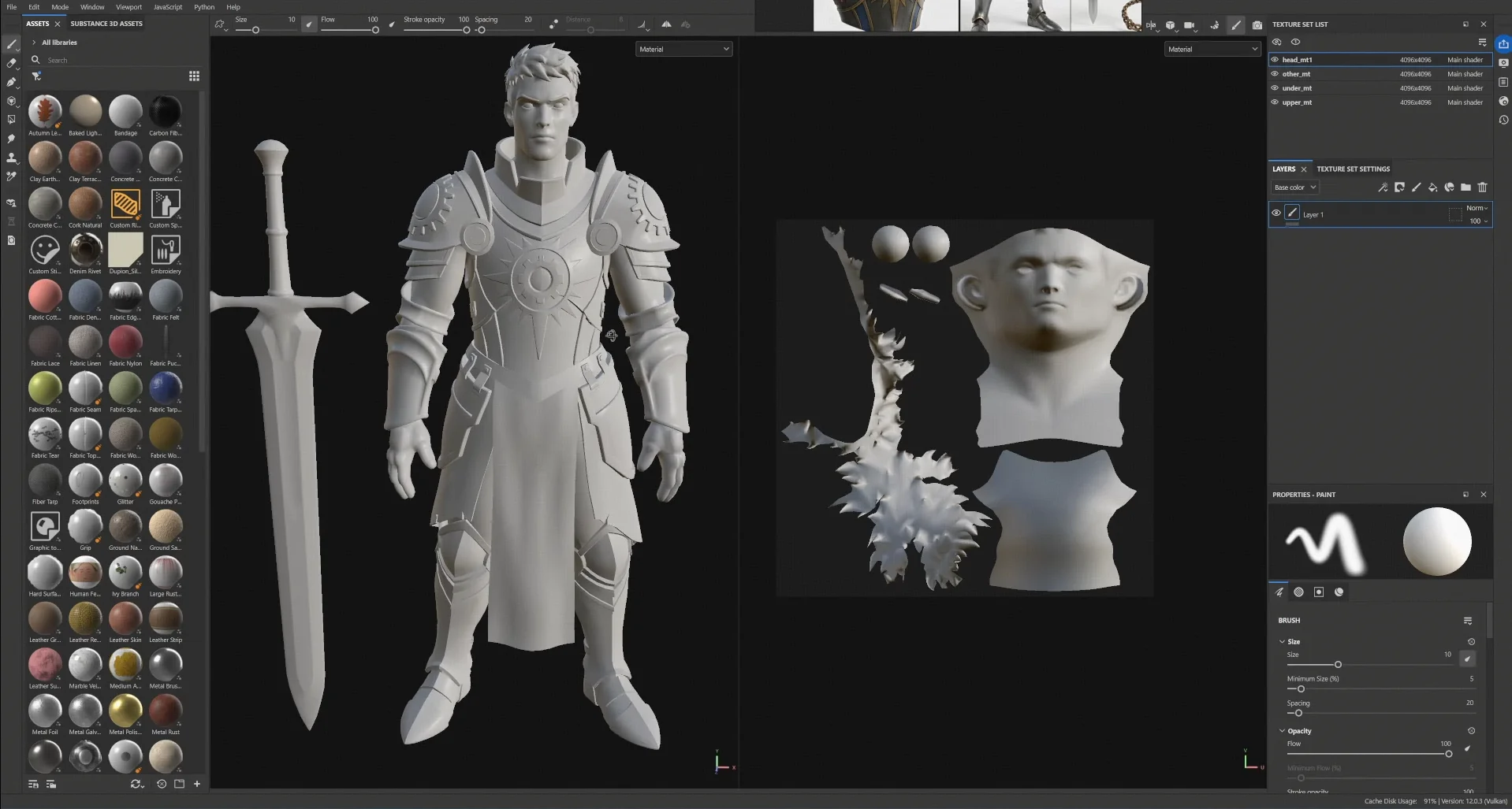
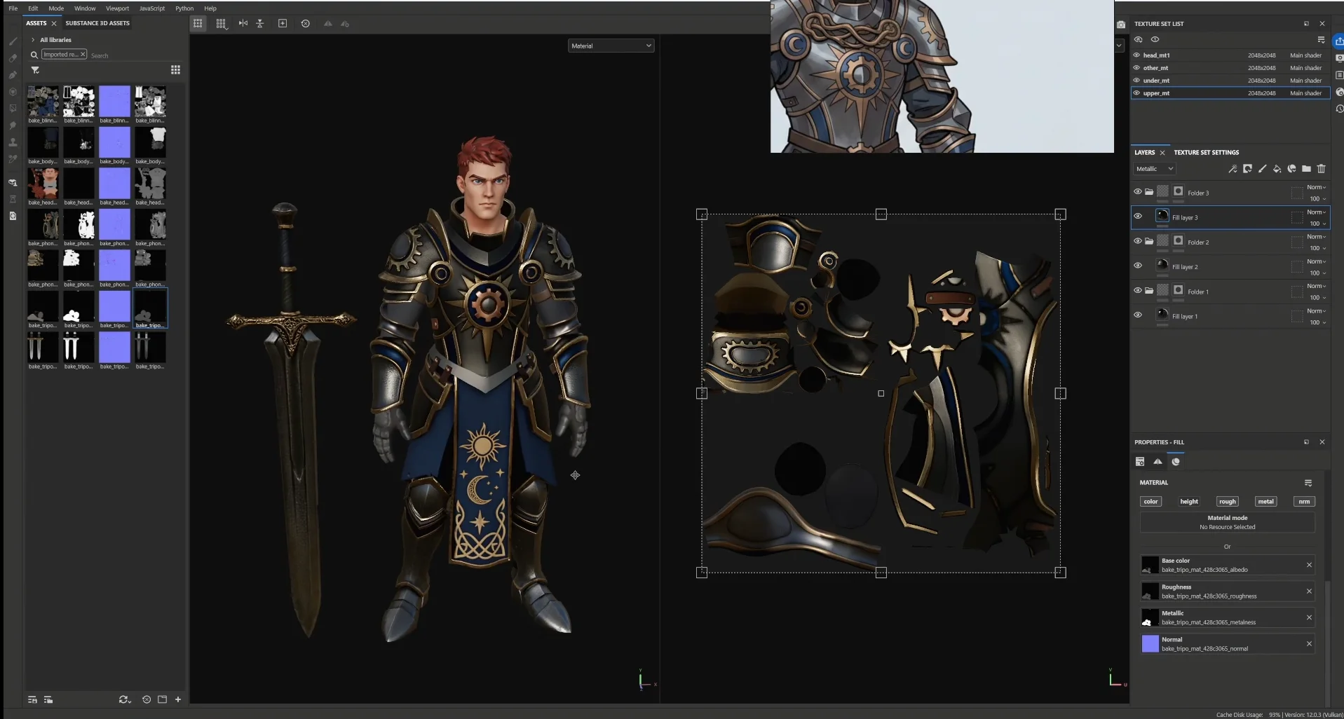
This is where artistic skill differentiates the result. Everything upstream exists to make sure this step gets the time it deserves.
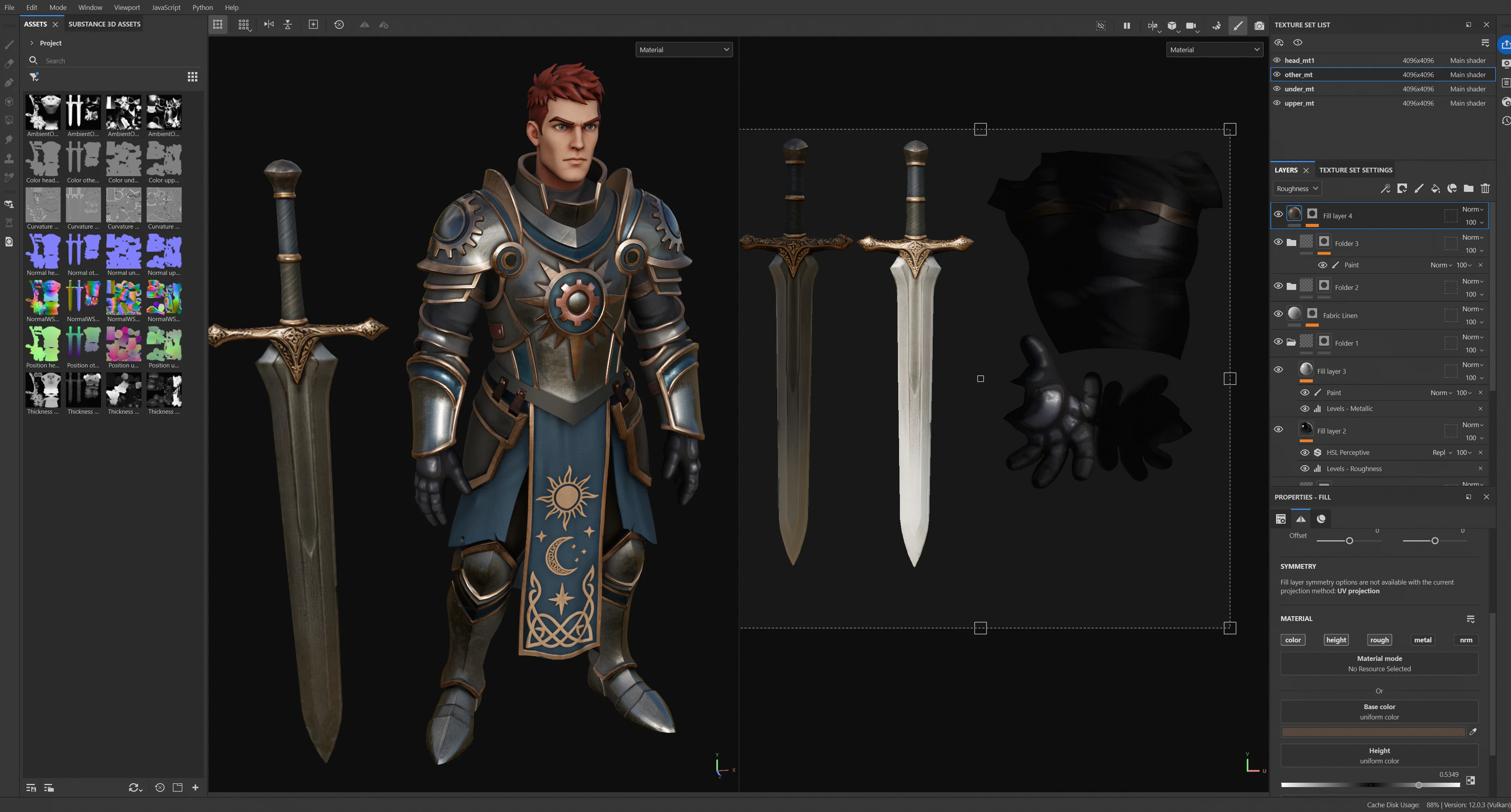
Step 14 — Rigging and Animation
Rigging and animation are not yet at industry standard within this pipeline. Custom rigging remains the recommendation for production characters.
That said, clean topology is the precondition for a good rig — and that is precisely what the earlier phases deliver.
Step 15 — Engine Integration
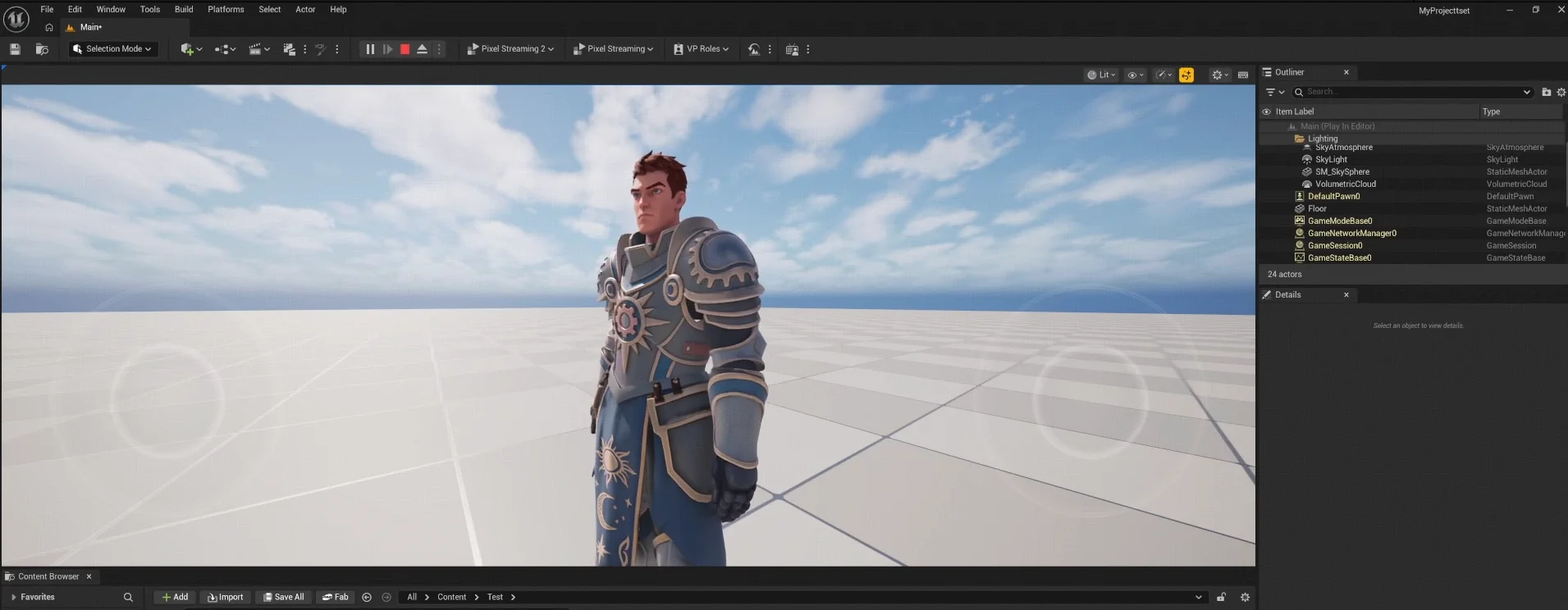
Import into the engine and assign materials with the correct texture set.


.webp?x-oss-process=image%2Fresize%2Cw_720%2Fformat%2Cwebp%2Fquality%2Cq_80)