AI Product Prototype to 3D Print: A Practical Workflow
TL;DR
- The fastest path to a physical prototype is now: AI generates the model, you clean the mesh, then slice and print.
- AI image/text-to-3D replaces hours of CAD for early concept models—but not for precision-fit engineering parts.
- The step most overviews skip: fixing AI-generated geometry (holes, non-manifold edges) so it's actually printable.
- Match the printer to the part: FDM for cheap functional prototypes, SLA/resin for fine detail.
- Export STL for geometry-only workflows or 3MF when a compatible export-and-slicing workflow needs to preserve color, material, texture, or project data; then set units to mm and slice.
To go from a product idea to a 3D-printed prototype with AI: describe or upload your concept, generate a 3D model with an AI image-to-3D tool, clean the mesh so it's watertight, choose a print process (FDM or resin), then export an STL and slice it. This guide walks the full workflow—plus when AI beats CAD, what it costs, and the IP rules.
Why AI Changes Product Prototyping
For makers, independent inventors, and early-stage hardware teams, the hardest part of prototyping is often not the printer. It is getting a product idea into a usable 3D model.
Traditional prototyping usually follows a familiar path: sketch an idea, learn CAD, build the model manually, export it, print a test, find problems, return to CAD, and repeat. That workflow remains essential for precise engineering work, but it can be slow when the goal is simply to turn an early concept into something physical.
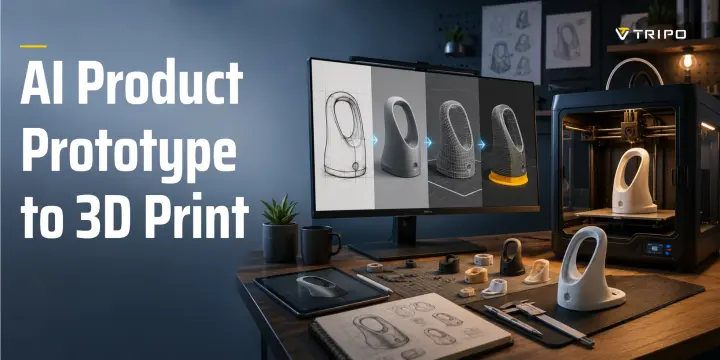
AI introduces a practical third route between hand sketches and full CAD construction. A maker can begin with a written description, rough sketch, product photo, or concept image, generate a 3D starting mesh, repair it for printing, and produce an early physical prototype without waiting until a complete CAD model is finished.
AI does not eliminate prototyping work. It accelerates the first translation from an idea to a tangible form.
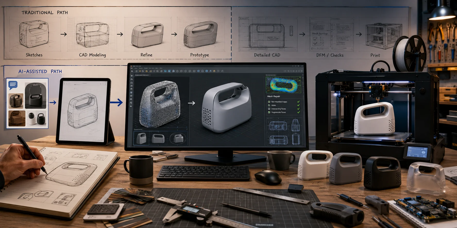
The Old Loop vs. the AI Loop
The traditional loop is:
Sketch → CAD model → export → slice → print → revise CAD
The AI-assisted loop is:
Prompt or photo → AI mesh → repair → slice → print → revise prompt, mesh, or CAD details
Traditional CAD is strongest when a product requires exact dimensions, threads, snap fits, mechanical tolerances, or engineering validation. AI is strongest when the first question is visual and conceptual:
- What should this product look like?
- Does this grip feel too large?
- Is this enclosure shape practical?
- How does this concept look on a desk?
- Can users understand the object’s purpose?
- Is the proportion right before we invest in detailed engineering?
For many early concepts, holding a rough physical version is more useful than staring at a flat sketch.
Who This Workflow Is For
This workflow is useful for:
- makers developing a personal invention;
- students building prototype portfolios;
- independent product designers;
- startup teams validating product form;
- ecommerce teams testing product concepts;
- industrial-design beginners without deep CAD experience;
- founders who need an early object for pitch photos, user feedback, or discussion.
It is especially useful for appearance models, ergonomic studies, early enclosures, decorative products, consumer-accessory concepts, packaging forms, handles, housings, tabletop objects, and product mockups.
It is not a replacement for engineering design. Treat it as a fast way to move from “idea” to “first physical question.”
Step 1 — Turn Your Product Idea Into a 3D Model
AI generation begins with choosing the right input. You can start from text when you only have an idea, or from an image when you already have a sketch, reference, or visual direction.
The goal is not to generate a glossy render. The goal is to create geometry that can become a printable prototype.
For printing, prioritize form, proportion, surface continuity, and structural simplicity before worrying about textures.
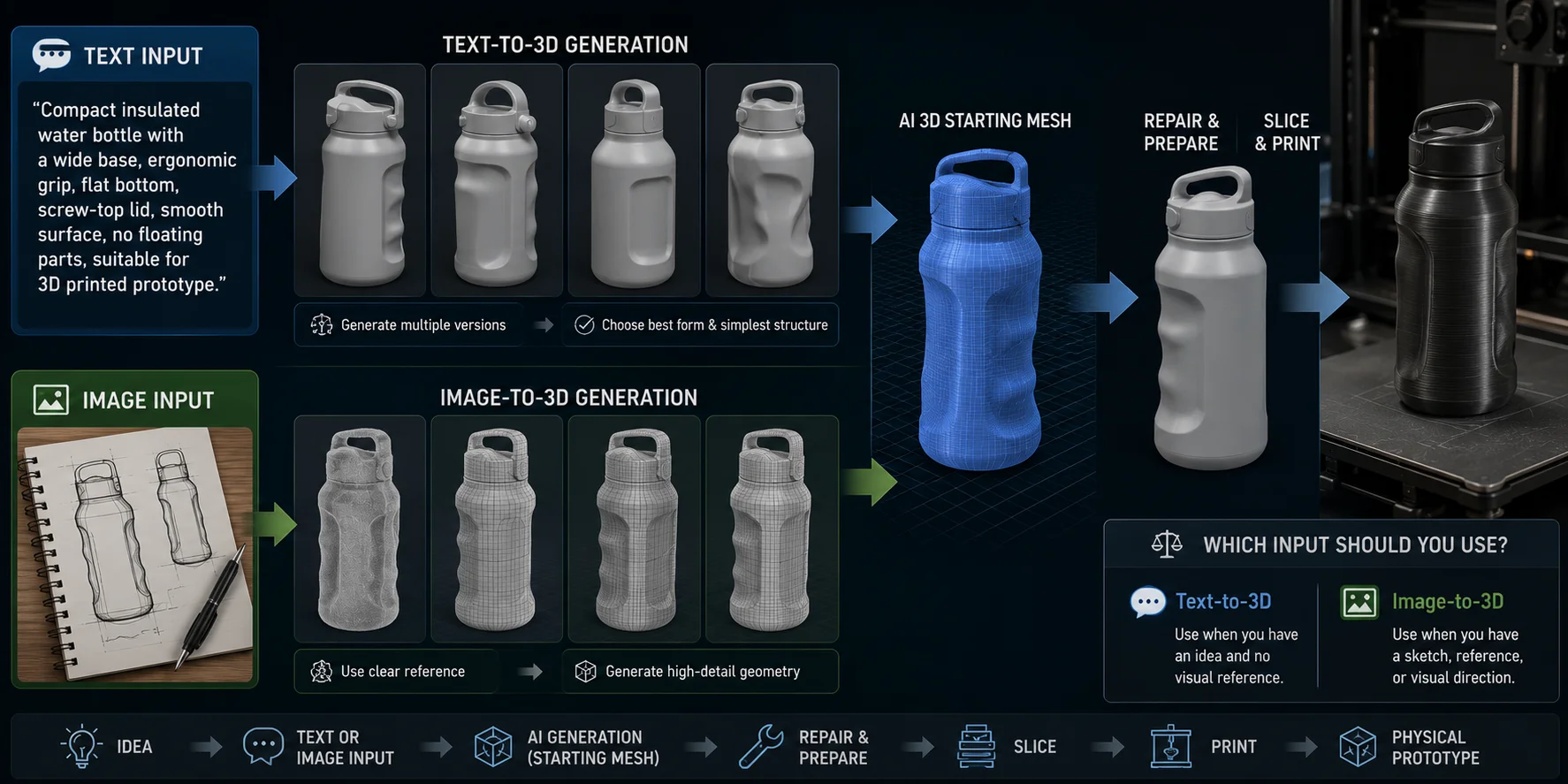
Text-to-3D: Start From an Idea
Text-to-3D is useful when the product is original and you do not yet have a finished drawing.
A vague prompt such as “smart water bottle” may create an attractive concept, but it gives little guidance about shape or manufacture. A more useful prompt describes the product’s structure and physical constraints:
Compact insulated water bottle with a wide base, ergonomic finger grip, flat bottom, simple cylindrical body, screw-top lid, smooth outer surface, no floating parts, suitable for 3D printed prototype.
Useful prompt details include:
- overall shape;
- intended use;
- flat or stable base;
- handle or grip position;
- symmetry;
- broad surfaces;
- simple opening locations;
- thickness cues;
- lack of thin spikes or floating parts;
- removable components;
- low-profile decoration.
Tripo AI Text to 3D can generate a starting 3D model from a written description. Generate several versions rather than relying on the first output. Choose the version with the clearest silhouette, simplest structure, and fewest fragile or visually confusing details.
Image-to-3D: Start From a Sketch or Reference
Image-to-3D is usually better when you already have a sketch, product concept board, hand-drawn silhouette, photographed mockup, or reference object.
Use an image with:
- one clearly visible subject;
- centered framing;
- high contrast between product and background;
- minimal shadows and clutter;
- little or no text covering the object;
- visible outer shape;
- no hands hiding important surfaces.
For a product enclosure, a front, side, or three-quarter view usually works better than a dramatic perspective illustration. For a handle, housing, or container, aim for an image that makes the main volume obvious.
Tripo AI Image to 3D can turn one image into a 3D starting mesh. For print-oriented prototype work, use a geometry-focused, high-detail workflow when available. A detailed model can preserve form and surface character, but it still needs printability checks.
Text vs. Image Input: Which Should You Use?
Use text-to-3D when the product is still an idea, when you are exploring multiple directions, or when no suitable visual reference exists.
Use image-to-3D when you already have a sketch, reference image, product illustration, or rough physical mockup that defines the intended silhouette.
A simple decision rule is:
- Have a clear visual direction? Use image-to-3D.
- Have only a product idea? Use text-to-3D.
Both routes create an early model. Neither automatically creates a fully engineered product.
Step 2 — Make the AI Model Printable
A generated model may look convincing in a preview but still fail when imported into a slicer. The difference between a visual mesh and a printable mesh is technical: the model must be closed, coherent, scaled correctly, and thick enough to fabricate.
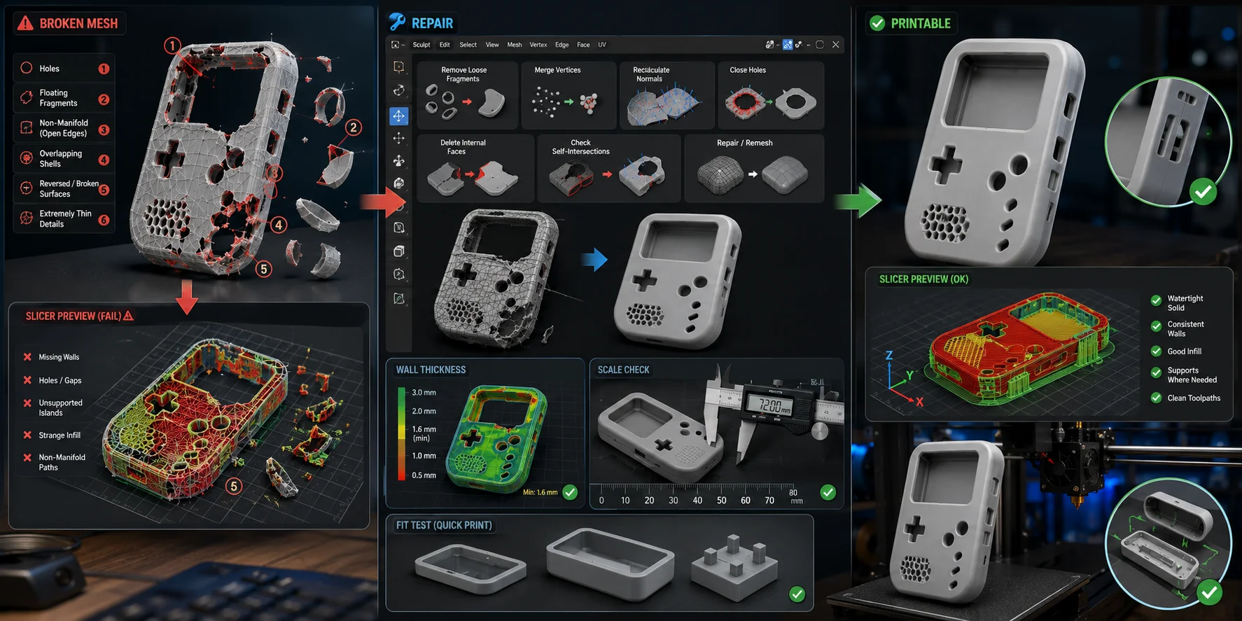
Why AI Meshes Break the Slicer
A slicer needs a valid solid volume to calculate walls, infill, supports, and toolpaths. AI-generated meshes may contain:
- holes;
- non-manifold edges;
- reversed normals;
- overlapping shells;
- self-intersections;
- floating fragments;
- disconnected parts;
- internal faces;
- open bottoms;
- very thin details.
A non-manifold mesh does not describe a physically valid solid. An edge may be shared incorrectly, a surface may have no thickness, or intersecting shells may confuse the slicer.
When a mesh is non-manifold, the slicer may create missing walls, odd infill, unsupported islands, invisible sections, or toolpaths that fail later in the print.
High-detail generation can add more geometry to inspect. A Tripo HD Model generated at a 2M-triangle setting can preserve curves and product detail for 3D-printing prototypes, but more triangles do not guarantee a watertight or printable shell. Detail improves appearance; it does not replace mesh validation.
Fix It
Open the model in Blender, Meshmixer, or another mesh-editing tool before slicing. Meshmixer can still be useful for quick repair, but Autodesk no longer develops or supports it, so use a maintained alternative when possible.
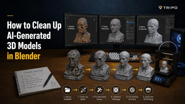
A practical repair order is: remove loose fragments and internal faces; close holes and fix non-manifold edges; recalculate normals; join only the parts that should form one body; then check for self-intersections and remesh only where necessary. In Blender, the common repair tasks are:
- removing loose fragments;
- merging nearby vertices;
- recalculating normals;
- closing holes;
- deleting internal faces;
- joining intended separate parts;
- checking self-intersections;
- remeshing where needed.
Blender’s 3D Print Toolbox can help identify non-manifold edges, intersecting faces, thin walls, and loose geometry. The goal is not perfect mathematical geometry; it is one coherent printable volume.
Meshmixer can quickly identify and repair holes. Remeshing may improve continuity, but aggressive remeshing can soften sharp edges, symbols, and delicate features.
Many slicers include basic repair tools, but use them as a final check rather than the only repair method. If the slicer changes the model automatically, inspect the layer preview carefully.
Also preserve intended openings. A container needs an opening, an enclosure may need an access port, a handle may need mounting holes, and a display stand may need a cable channel. Do not accidentally repair away functional features.
Wall Thickness and Scale
AI-generated models often arrive at arbitrary dimensions. Scale the object before slicing, then check wall thickness again.
Set units to millimeters and compare the model with the real object it must fit. Measure the phone for a stand, the hand for a grip, or the PCB, battery, and connectors for an enclosure.
Wall thickness depends on material and purpose. A decorative shell can be thinner than a bracket, while snap-fit parts need tighter dimension control than display objects.
For FDM, use enough wall thickness to survive handling, sanding, and basic testing. SLA can produce very thin details, but standard resin may crack under repeated use.
Always print a small fit sample when the model interacts with another object. Test connector clearance, button openings, screw-hole alignment, lid fit, cable channels, grip comfort, and enclosure thickness. A short test print can prevent a full-day failure.
Step 3 — Choose Your Print Process: FDM vs. SLA
The right print process depends on what the prototype needs to prove.
For size, grip, assembly, or early strength checks, FDM is usually the practical first choice.
Are you testing small details, smooth surfaces, complex curves, or a premium appearance model? Use SLA or resin printing.
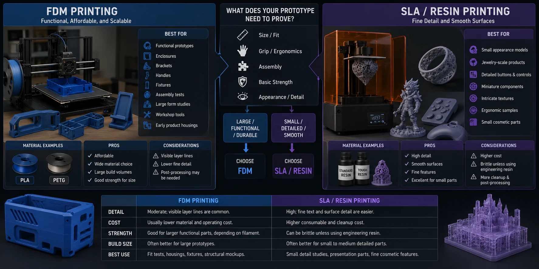
FDM: Functional, Affordable, and Scalable
FDM printers build parts by extruding melted filament layer by layer. They are common because they are relatively affordable, material-efficient, and suitable for larger objects.
FDM is usually the best choice for:
- functional prototypes;
- enclosures;
- brackets;
- handles;
- fixtures;
- assembly tests;
- large form studies;
- workshop tools;
- early product housings.
PLA is easy to print for appearance models and early prototypes. PETG offers more impact resistance and is often better for practical parts exposed to repeated handling.
FDM surfaces show visible layer lines, but those usually do not matter during early testing. For presentation models, sanding and primer can improve the finish.
SLA / Resin: Fine Detail and Smooth Surfaces
SLA and resin printers cure liquid resin with light. They usually produce finer surface detail and smoother curves than common FDM printers.
SLA is useful for:
- small appearance models;
- jewelry-scale products;
- detailed buttons and controls;
- miniature components;
- intricate textures;
- ergonomic samples with smooth curves;
- small cosmetic parts.
However, resin printing usually involves washing, curing, gloves, ventilation, and more post-processing. Standard resin can also be brittle, so it may not be the right choice for clips, brackets, or impact-tested functional components.
| Factor | FDM Printing | SLA / Resin Printing |
|---|---|---|
| Detail | Moderate; visible layer lines are common. | High; fine text and surface detail are easier. |
| Cost | Usually lower material and operating cost. | Higher consumable and cleanup cost. |
| Strength | Good for larger functional parts, depending on filament. | Can be brittle unless using engineering resin. |
| Build size | Often better for large prototypes. | Often better for small to medium detailed parts. |
| Best use | Fit tests, housings, fixtures, structural mockups. | Small detail studies, presentation parts, fine cosmetic features. |
Choose the process based on the question your prototype must answer, not purely on surface quality. Select the material and print orientation based on the direction of load, the failure mode you need to evaluate, and the specific behavior the test is meant to reveal.
Step 4 — Export, Slice, and Print
Once the model is repaired and scaled, export it to a printing workflow.
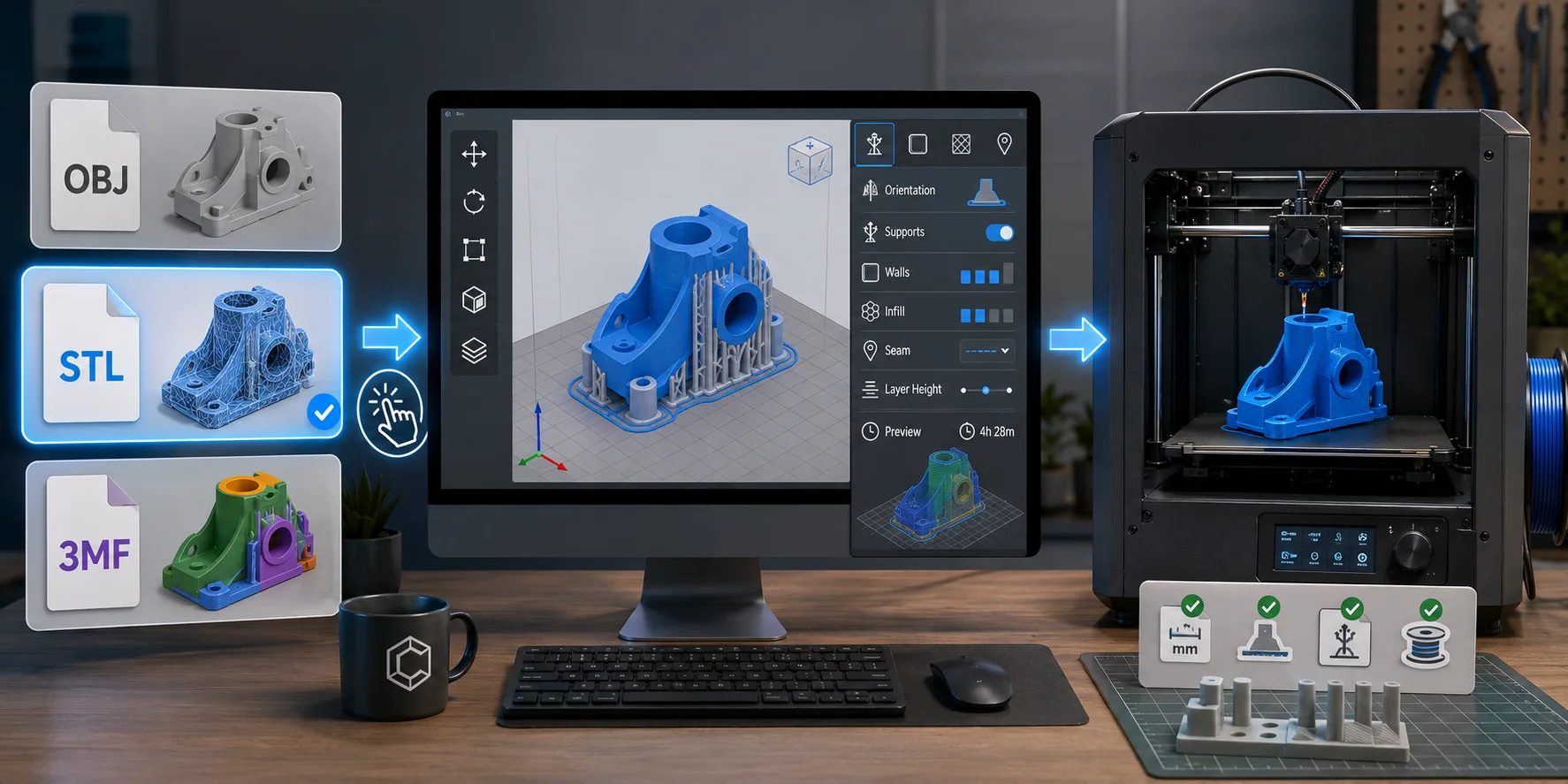
STL vs. 3MF: Which Should You Choose?
Choose the export format based on the printing workflow.
- OBJ: a basic 3D format that can be used in some 3D printing workflows.
- STL: the standard 3D printing format for geometry-only files.
- 3MF: a modern 3D printing format that may preserve color, material, texture, or project data when the export and slicing workflow supports it.
For a single-material functional prototype, STL is usually the simplest choice because most slicers support it and it contains the geometry needed for printing.
Choose 3MF when a compatible export and slicing workflow needs to preserve multiple parts, color, material, texture, or printing-specific project data. Tripo can also export formats such as GLB, USD, and FBX for visualization, rendering, or downstream workflow needs. Export availability can vary by plan and model version, so check the current options shown in Tripo Studio before starting a production workflow.
Prepare the Print in Your Slicer
Import the file into Bambu Studio, Cura, PrusaSlicer, OrcaSlicer, or your preferred slicer.
Before printing, review:
- scale in millimeters;
- orientation;
- build-plate contact;
- support placement;
- wall count;
- infill;
- seam position;
- layer height;
- estimated material use;
- print time.
Tripo Studio supports one-click sending of compatible models to Bambu Studio. The model is sent in 3MF format, which reduces manual download and import steps. The one-click path is for monochrome printing; for color workflows, export a multi-color printable file and import it manually. Still, always inspect the model inside the slicer before printing.
For functional FDM prototypes, start with moderate wall count and infill, then increase material only where needed. A first print should answer the core question as quickly as possible.
Do not print the final full-size version first. Test a small section when tolerances, mounts, clips, lids, or interfaces matter. For a phone stand, print the slot and base-contact area first; for an enclosure, test the connector panel or a screw-boss corner before committing to the full housing.
Step 5 — Iterate Fast
The value of a prototype is not that it looks perfect. Its value is that it gives you evidence quickly.
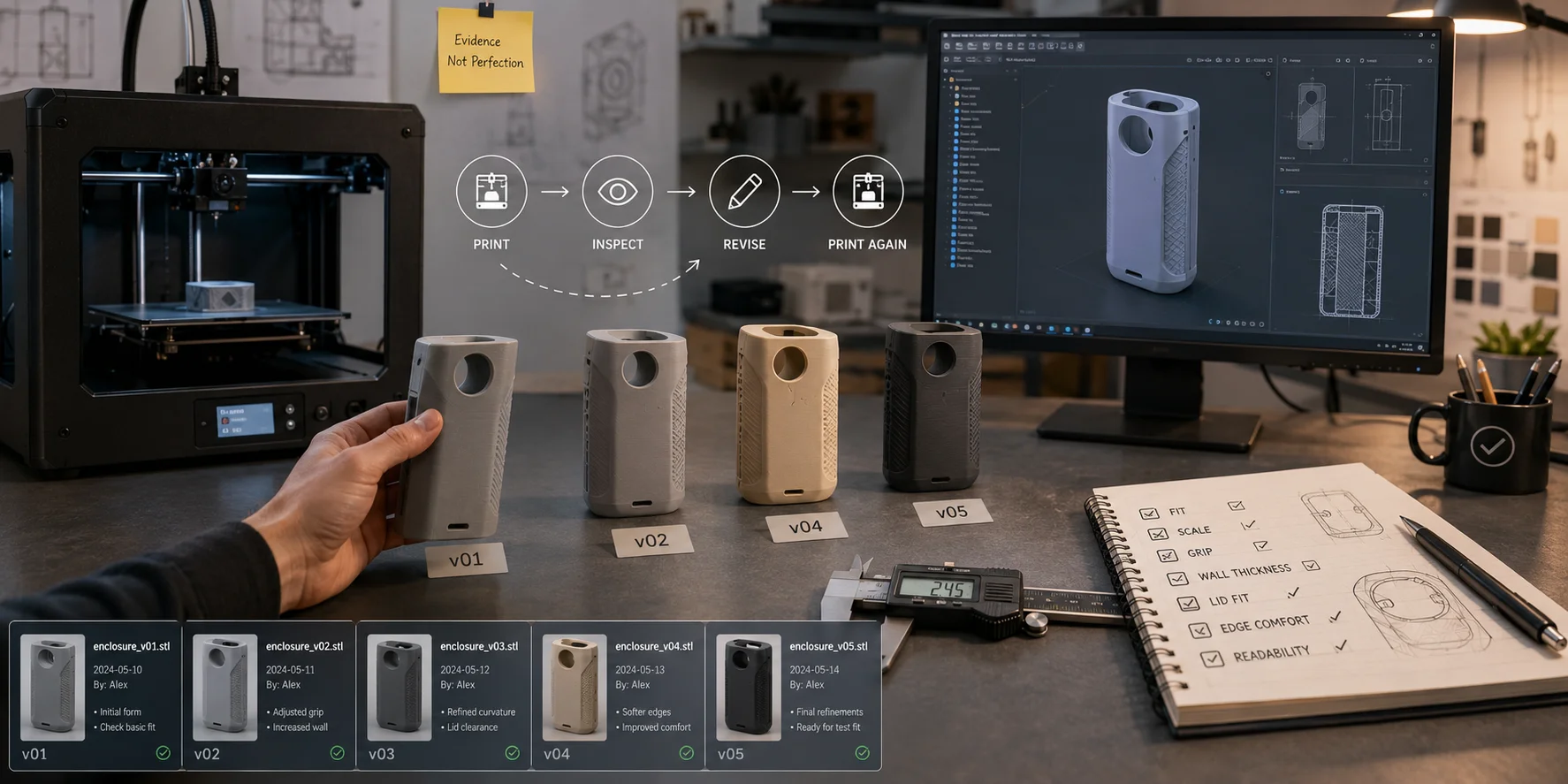
After every print, ask:
- Does it fit?
- Is the scale right?
- Is the grip comfortable?
- Is the wall too thin?
- Is the lid too loose?
- Are the edges too sharp?
- Is the product readable from a distance?
- Did the print reveal an unexpected problem?
Then revise the fastest variable.
You may change:
- the prompt;
- the reference image;
- the model scale;
- local mesh geometry;
- wall thickness;
- split lines;
- print orientation;
- material choice;
- CAD details.
Keep simple version records. Name files clearly, such as:
housing_v01.ai_meshhousing_v02_scaledhousing_v03_wallfixhousing_v04_printtesthousing_v05_cad_refined
Also record what changed and why. A prototype process becomes expensive when the team cannot remember which version solved which problem.
Move to CAD when the design reaches the stage where exact engineering matters: screw bosses, mating surfaces, threads, snap fits, mounting points, seals, electronics, safety-critical interfaces, or repeatable manufacturing dimensions.
AI helps you reach the question. CAD helps you lock the answer.
AI Generation vs. Traditional CAD: Which Should You Use?
| Factor | AI 3D Generation | Traditional CAD |
|---|---|---|
| Speed | Fast for early concepts and visual forms. | Slower initially, especially for beginners. |
| Learning curve | Lower for concept generation from prompts or images. | Higher because users must learn sketches, constraints, dimensions, and features. |
| Geometric accuracy | Variable; usually needs inspection and cleanup. | High; built around controlled dimensions and constraints. |
| Tolerance control | Weak for precise fit and repeated assemblies. | Strong for threads, snap fits, holes, mounts, and engineered interfaces. |
| Best prototype stage | Form exploration, appearance models, concept validation. | Functional refinement, fit testing, manufacturing handoff. |
The most practical workflow is often hybrid.
Use AI to explore form quickly. Use a printed AI model to test size, comfort, visual direction, and user reaction. Then rebuild or refine critical areas in CAD once the concept is proven.
For example, AI can generate the outer form of a handheld device, while CAD defines the battery compartment, screw bosses, connector cutouts, vent pattern, and mounting features.
AI is not better than CAD. It is faster at one kind of problem.
What It Costs and the IP Question
Cost
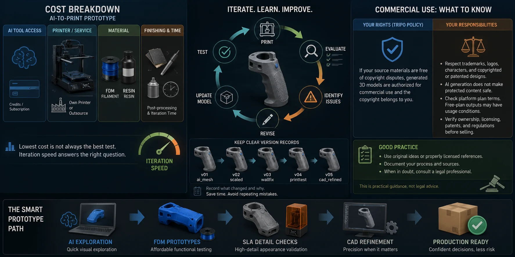
The cost of an AI-to-print prototype depends on four categories:
- AI tool access or credits;
- printer ownership or outsourced print service;
- material;
- finishing and iteration time.
A home FDM printer can make early prototyping economical because filament is inexpensive relative to repeated outsourced production. Resin printing costs more in consumables and cleanup, but it can be worthwhile for small high-detail appearance models.
For startups, the most important cost is usually not material. It is iteration speed. A low-cost prototype that answers the wrong question is more expensive than a slightly better test that prevents a redesign later.
Use AI for early visual exploration, FDM for affordable functional testing, SLA for detailed appearance checks, and CAD only when precision justifies the time.
Can You Sell What You Print?
Commercial use involves two separate issues: the rights granted by the AI platform under your current plan and your rights to the underlying product concept or source material.
Commercial rights depend on the current plan terms and the rights in the source materials. Do not assume that an output created on a free tier may be sold, even if the generated model appears original.
However, this does not remove every legal responsibility. A reference image may contain someone else’s protected product, logo, character, trademark, patented design, or copyrighted artwork. AI generation does not automatically make that source material safe to commercialize.
Before selling, review the current plan terms and confirm the rights for every source image, logo, character, product design, and brand element used in the workflow.
This is a workflow guide, not legal advice. For a commercial product line, verify ownership, licensing, trademarks, patents, and applicable regulations before selling.
When This Workflow Does Not Work
AI-to-print workflows are not the best solution for every prototype.
Use CAD or engineering processes when you need:
- precision fits;
- tolerance-sensitive assemblies;
- threaded features;
- snap-fit mechanisms;
- complex internal channels;
- electronics mounting;
- structural simulation;
- load-bearing validation;
- safety-critical geometry.
AI-generated models also struggle with ultra-thin walls, highly precise interfaces, complex hidden internal structures, and parts that must match manufacturing constraints exactly.
For a product that will carry weight, contain pressure, support a person, manage heat, or protect electronics, do not rely on a visually convincing AI mesh alone. Move into measured CAD, material testing, engineering analysis, and repeated validation.
AI is most valuable at the beginning of the product journey. Engineering becomes more important as the consequences of failure increase.
Frequently Asked Questions
Can AI design a 3D print model?
AI can generate a 3D starting model from a prompt, sketch, or reference image. It can be useful for concept models, appearance prototypes, and early form exploration. Before printing, inspect the mesh for holes, non-manifold geometry, wall thickness, scale, and slicer errors.
Can ChatGPT actually make STL files?
ChatGPT can help write scripts for simple models, explain CAD steps, or generate OpenSCAD code for basic geometric parts. It does not reliably replace dedicated 3D modeling tools for complex printable products. For visual concepts, use an AI 3D generator, then repair and validate the output before printing.
Why does my AI-generated 3D print keep failing?
The most common causes are holes, non-manifold edges, reversed normals, unsupported islands, thin walls, incorrect scale, or weak print orientation. Repair the mesh in Blender or another maintained mesh-editing tool, then inspect the sliced preview layer by layer. Print a small test section before committing to a full prototype.
What file format do I need to 3D print an AI model?
STL is the standard choice when you only need printable geometry. 3MF is useful when a compatible export and slicing workflow needs to preserve color, material, texture, or printing-focused project data. Most slicers can import both formats.
Is AI-generated 3D modeling better than CAD for prototypes?
AI is faster for early concept exploration and appearance testing. CAD is better for dimensions, tolerances, functional assemblies, and manufacturing-ready parts. Many teams use AI for early form studies, then use CAD to refine critical features.
Can I legally sell a product I 3D printed from an AI design?
You may have commercial rights to an AI-generated model under the relevant platform terms, but you must still verify the source image, branding, product design, patents, trademarks, and other intellectual-property issues. AI generation does not automatically remove legal restrictions.
Conclusion
Your product idea can become a physical prototype today: generate the model with AI, repair the mesh, choose the right print process, export it, and test it in your hands.
The first print will rarely be the final design. That is normal. Prototype quickly, measure what fails, refine the model, and use CAD when precision becomes essential. Start with your first concept in Tripo AI Studio.