UV Mapping Explained: What It Is & How to Do It
TL;DR
- UV mapping is the process of unfolding a 3D model's surface into a flat 2D layout so textures can be applied without stretching or seams.
- The U and V axes define the horizontal and vertical coordinates of that 2D texture space.
- Good UV unwrapping in Blender involves marking seams, running the unwrap algorithm, and optimizing the UV island layout.
- Common problems—stretching, overlapping UVs, and wasted space—each have specific repair strategies covered in this guide.
- AI texturing tools like Tripo can generate textures and skip manual UV work entirely, which is especially useful for beginners.
UV mapping is the process of unwrapping a 3D model's surface into a flat 2D layout so a texture can be applied accurately. The "U" and "V" are the 2D axes of that texture space. Good UV maps prevent stretching and seams—and AI texturing tools can now generate them automatically. This article will systematically explain UV mapping and its common issues, and introduce how to avoid manual UV unwrapping in the AI era through fully automated AI Texturing.
What Is UV Mapping?
In the production process of 3D games, animated films, and VR/AR content, most beginners will encounter a common problem: Once texture maps are directly applied to the models, problems such as texture distortion, pattern misalignment, and image fragmentation will occur. The originally exquisite models will become strange and deformed.
The key issue lies in the lack of a crucial technology that connects a 2D layout with a 3D model: UV mapping.
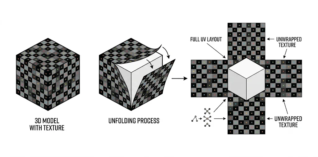
UV mapping is the process of splitting and flattening the surface of a 3D model according to standard geometric rules and converting it into a regular 2D layout. Creators can then draw and apply texture maps on the expanded layout, achieving a precise fit between the texture and the 3D model.
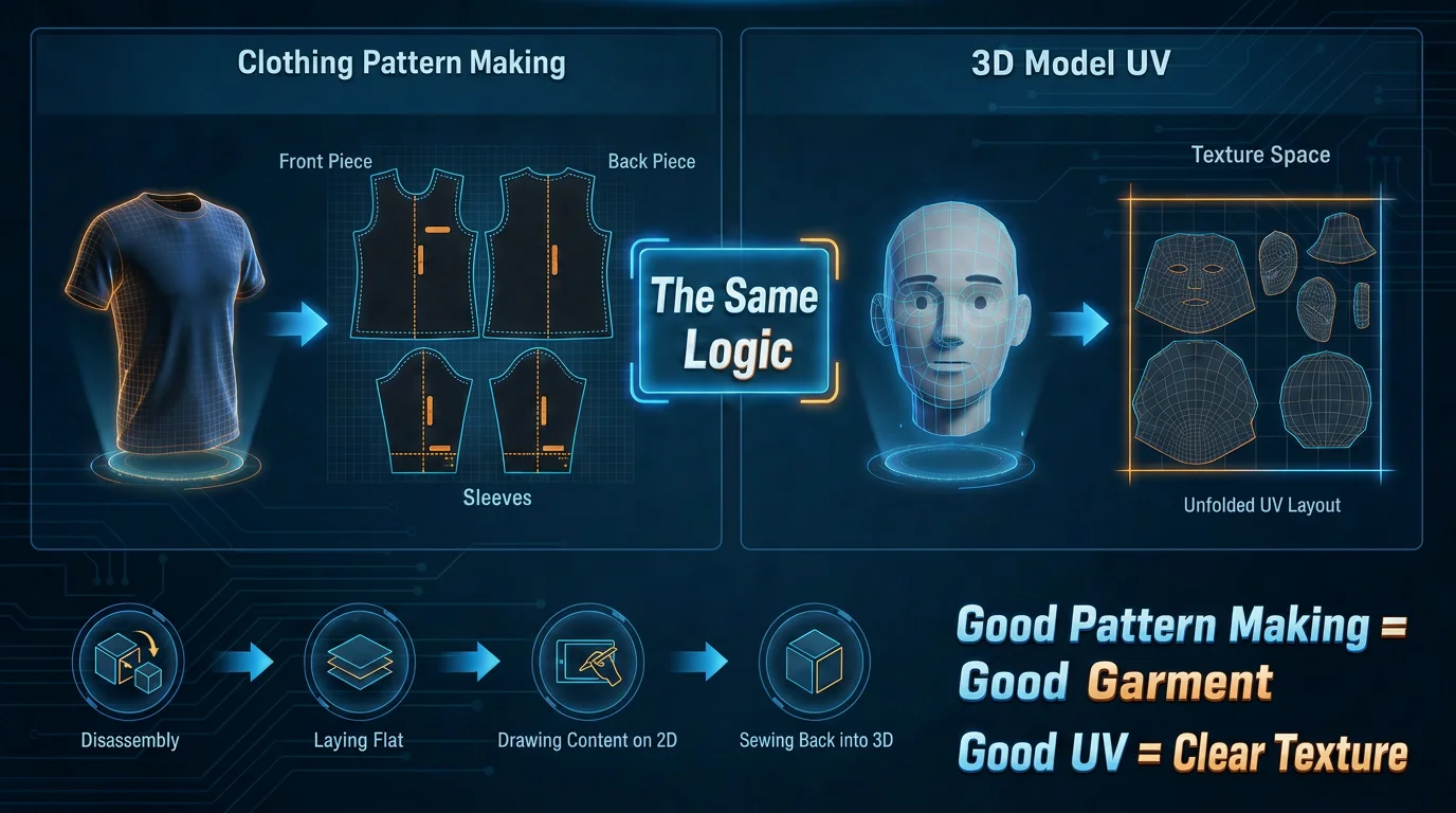
A simple way to understand UV mapping is to compare it to making a sewing pattern. Before making clothes, a designer turns a three-dimensional garment into flat fabric pieces, cuts them, and then stitches them back together. UV mapping does something similar for 3D models:
- It cuts the model's 3D surface into workable pieces.
- It lays those pieces flat in a 2D texture space.
- Artists paint or generate textures on that 2D plane, and the engine maps those pixels back onto the 3D model.
The U and V axes are simply the two coordinate directions on that flat texture plane. They are called U and V because X, Y, and Z are already used by the 3D model's spatial coordinates. A well-made clothing pattern helps the garment fit without distortion; a well-made UV map helps textures stay clear and unstretched when they are projected back onto the model.
Why UV Mapping Matters for Texturing
UV mapping is an indispensable core process in 3D visual creation. The quality of the UV map directly determines the model's visual authenticity, texture consistency, and rendering quality.
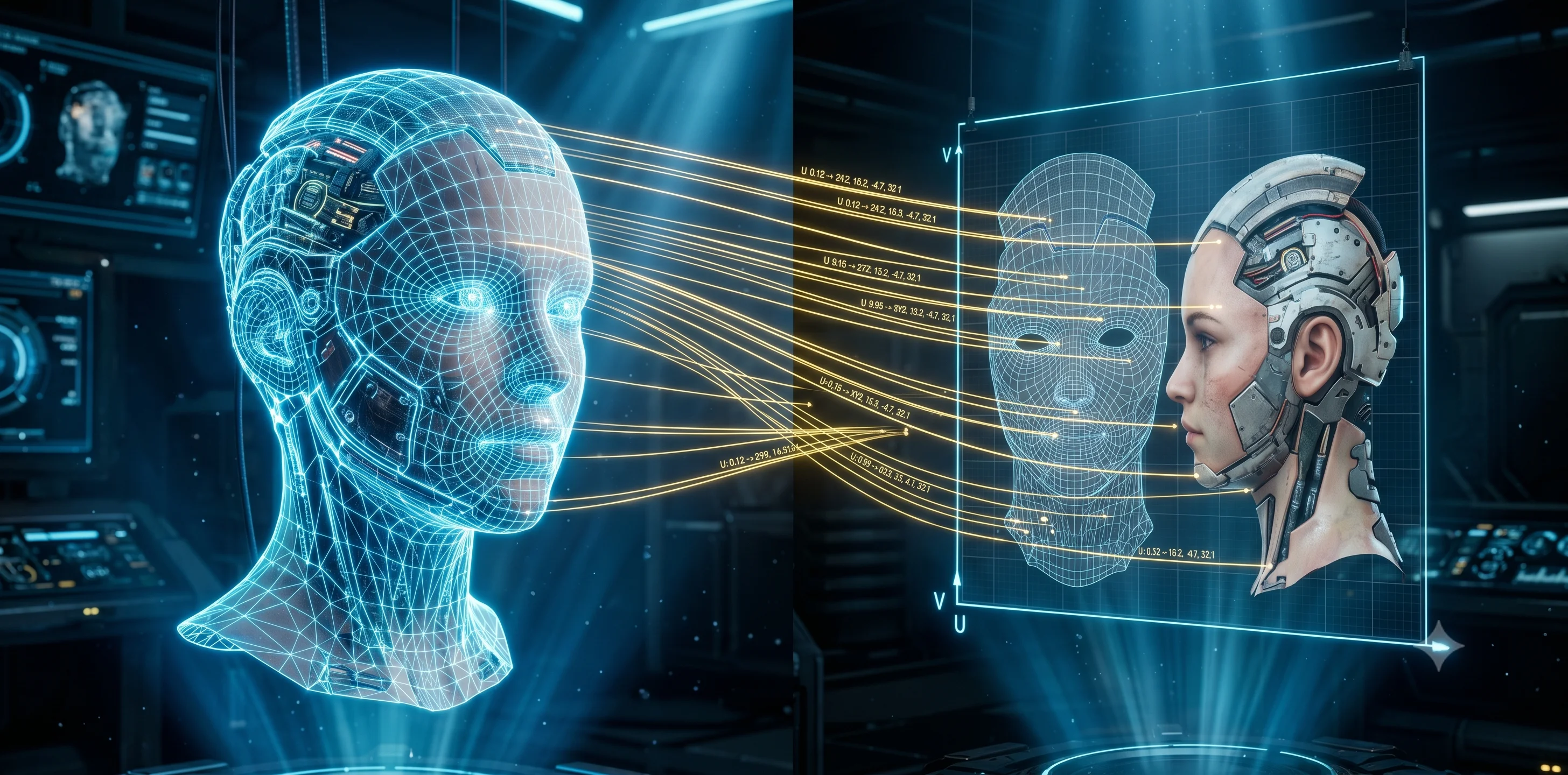
Through UV mapping, the U and V coordinates of the two-dimensional layout can be established with a one-to-one mathematical mapping relationship to the geometric vertices of the 3D model.
If UV is missing or of poor quality, it will cause severe misalignment and distortion of the texture pattern, and even prevent normal display. Excellent UV not only enables precise correspondence but also efficiently presents the correct and natural visual effect of the material, achieving a more delicate and beautiful texture image.
Texture Size Is Not the Same as Texture Quality
A common misunderstanding is that using a 4K texture automatically makes a model look sharp. Texture size only describes the total number of pixels; how useful those pixels are depends on the UV layout.
- High UV utilization: If UV islands use most of the texture space, more pixels are assigned to visible model surfaces, so the result looks sharper.
- Low UV utilization: If half of the texture space is empty or poorly packed, even a 4K map can behave like a much lower-detail texture in practice.
Model scale also matters. A small prop such as a cup may look clear with a 1K texture because its surface area is limited. A full-body character using the same 1K texture may look blurry because each body part receives fewer pixels. The metric that connects texture size, model area, and UV scale is called texel density, or how many texture pixels are available per unit of model surface.
Doubling texture resolution is not free: moving from 1K to 2K quadruples the pixel count, and moving from 2K to 4K quadruples it again. That means more memory usage, larger files, and heavier rendering cost. The better workflow is to optimize the UV map first, then decide whether the texture truly needs a higher resolution.
Resolution vs. Texel Quality
| Concept | What It Means | Why It Matters |
|---|---|---|
| Resolution | The size of the texture container, such as 1K = 1024 x 1024 pixels or 4K = 4096 x 4096 pixels. | It tells you how many pixels are available in total, but not whether those pixels are used efficiently. |
| Texel quality | The amount of useful detail each pixel carries on the actual model surface. | High texel quality shows real variation such as pores, scratches, or grain; low texel quality looks flat or blurry even at high resolution. |
In practice, the right approach is to pack UV islands tightly, give important areas such as faces and hands more UV space, reduce less visible areas such as soles or back-facing surfaces, and only then choose the final texture size.
UV Unwrapping Basics
UV unwrapping basics consist of three key elements and a standard implementation process:
The Core of UV Unwrapping: Three Key Elements
- Seams: Acting like a tailor's cutting lines, seams designate exactly where the 3D model will be strategically split open.
- UV Islands: After the model is cut and flattened, these form independent planar grids in the 2D space.
- Layout: The meticulous, space-optimized arrangement of these UV islands within the normalized 0-to-1 square canvas to eliminate pixel waste.
Standardized DCC Production Pipeline
- Preparation & Cleanup: Check the model topology, then reset and apply scale to (1, 1, 1) to prevent inherent stretching during calculations.
- Seam Marking: Select edges with sharp turns or hidden positions, then mark them as seams.
- Algorithm Unwrapping: Trigger the unwrap command; the flattening algorithm automatically relaxes polygon tension along the seams to create 2D UV islands.
- Layout Optimization: Harmonize texel density across all islands to ensure uniform pixel distribution, then tightly pack the canvas like a game of Tetris.
- Quality Check: Project the checkerboard texture map, observe for any stretching deformation or seam misalignment, and make local fine-tuning adjustments.
What Makes a Good UV Map?
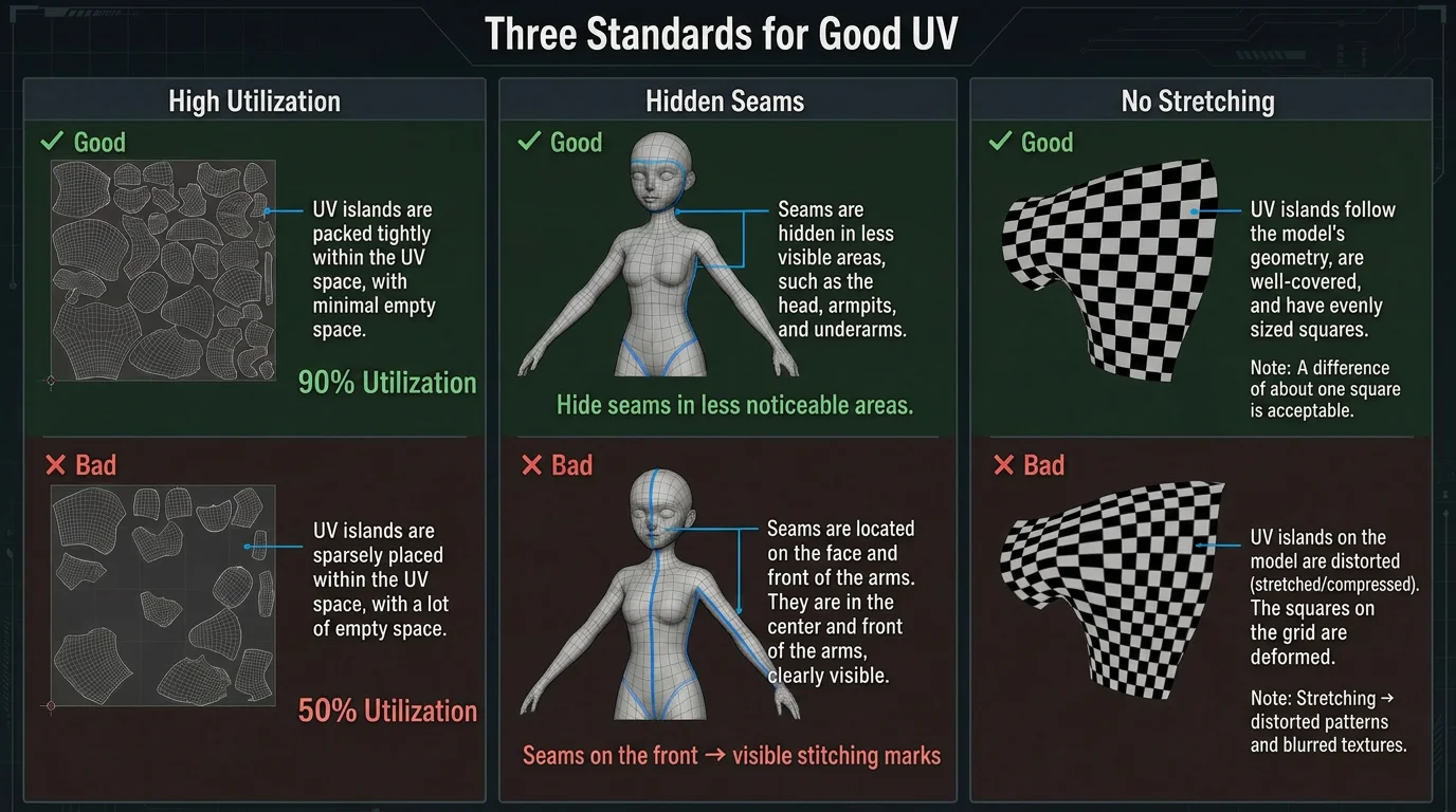
Before going into the step-by-step workflow, it helps to know what good UV mapping looks like. A strong UV map usually meets three standards:
- High utilization: UV islands are packed tightly with minimal blank space, so the same 2K texture can deliver more effective pixels.
- Hidden seams: Seams are placed where viewers are less likely to notice them, such as under hair, inside an arm, near clothing folds, or on the back of an object.
- Minimal stretching: UV island shapes keep a reasonable proportion to the 3D surface, so checkerboard tests stay square instead of bending into stretched rectangles.
These standards explain why the following workflow focuses on cleanup, seam placement, unwrapping, and layout optimization instead of simply increasing texture resolution.
How to UV Map (Step by Step)
Take Blender as an example. Here is the detailed process for standardizing manual UV unwrapping.
| Steps | Operation | Function |
|---|---|---|
| 1 | Preparation and Cleanup | Apply Transformations, Clean Topology |
| 2 | Marking Seams | Select Edges, Mark Seams |
| 3 | Unwrapping Algorithm | Switching to the UV Editing workspace, performing Unwrapping, Relaxation and Inspection |
| 4 | Optimizing Layout | Uniform Pixel Density, Arrange and Integrate |
Preparation and Cleanup
Before unfolding UV, it is necessary to ensure that the geometric data of the model is clean and has been correctly reset. Otherwise, it will cause distortion in the subsequent calculations.
- Apply Transformations: In Object Mode, select the model and press Ctrl + A, choose All Transforms or Scale. Make sure that the scaling ratio of the model in the right sidebar is restored to (1, 1, 1).
- Clean Topology: Enter Edit Mode, press A to select all, press M to choose Merge by Distance, and remove overlapping faces and free vertices.
Marking Seams
Seams tell the software along which edges to cut the 3D surface. The golden rule for marking seams is to hide them in less visible areas of the model.
- Select Edges: In Edit Mode, switch to Edge Selection Mode, then use Alt + left mouse button to cycle through and select the edges that will be cut.
- Mark Seams: After selecting the edges, press Ctrl+E to open the Edge menu and choose Mark Seam. The marked edges will be highlighted in orange/red.
Unwrapping Algorithm
- Switch to the UV Editing workspace: Click the top tab in Blender and switch to the "UV Editing" workspace. The left side shows the 2D UV editor, and the right side shows the 3D viewport.
- Perform Unwrapping: In the 3D viewport, press A to select all the faces of the model, press U, and choose the first Unwrap.
- Relaxation and Inspection: The software algorithm will automatically release polygon tension and flatten the model into UV islands in the left 2D space. Apply a "Checker" texture map in the 3D view and check whether the grid on the model surface is stretched or deformed. If so, return to step 2 to re-cut the seams or use the "Relax" tool on the left.
Optimizing Layout
To maximize the use of the UV space, avoid wasting memory, and maintain consistent pixel density.
- Uniform Pixel Density: Select all UV islands, then use the "Texel Density" tool in the right UV sidebar (N key) to calculate and set a uniform value, ensuring that each unit area of the model receives the same number of pixels. A third-party plugin called "Texel Density Checker" needs to be installed.
- Arrange and Integrate: In the UV menu, select "Pack Islands" and set a reasonable margin. The software will automatically arrange all UV islands compactly and evenly on the square canvas.
When dealing with complex organisms or large-scale production, manual seam cutting and arrangement remain extremely time-consuming and repetitive tasks.
For complex organic models, Tripo Smart Mesh can automatically generate clean, optimized, game-ready topology—so you spend far less time on manual cleanup before unwrapping.
Common UV Problems & How to Fix Them
In 3D visual creation, the quality of UV mapping directly affects the fineness of the final texture and the rendering effect. However, even experienced 3D artists often encounter typical problems such as UV stretching, overlap, and space waste when dealing with complex organic objects or precise machinery. The following, based on the appearance, root causes, and practical repair methods in actual production, concisely explains the solution strategies for various problems.
Stretching
- Symptom: After applying a texture to the model, the originally square test grid becomes rectangular or distorted, causing logos or material details to warp.
- Cause: Unreasonable 3D surface unfolding, uneven UV island distribution, and unbalanced scaling of individual islands can squeeze pixels and distort surface details.
- Specific repair strategy: Manually cut UV seams in areas prone to stretching, such as spheres, curved surfaces, and arc-shaped structures, to avoid forced flattening of the surface; use the software's "Relax UV (Unfold/Relax)" function to regularize island proportions and eliminate pixel squeezing; unify the texture density of the entire model, calibrate pixel accuracy in the core visual area, and keep UV island scaling consistent.
Overlap
- Symptom: Identical scratches or texture patterns appear on completely different parts of the model, or severe black shadow patches appear during light and shadow baking.
- Cause: Overlapping UV islands, incomplete splitting, and unseparated symmetrical structures can map multiple surfaces to the same texture area, resulting in texture disorder, baking artifacts, and incorrect lighting.
- Specific repair strategy: Conduct a global check of UV islands, separate and offset overlapping areas, and stagger stacked islands; except for special resource optimization needs, avoid sharing overlapping UVs for symmetrical models; remove redundant faces and overlapping islands to ensure that each surface corresponds to an independent UV area.
Wasted Space
- Symptom: The texture looks blurry in the final render, even with a 4K image, and the model details still lack refinement.
- Cause: Disorganized UV island arrangement, excessive spacing, and inconsistent size ratios waste texture resolution, reduce overall quality, and create unnecessary resource usage.
- Specific repair strategy: Use the software's automatic UV arrangement (Pack UVs) function to compactly integrate all UV islands and reduce invalid spacing; unify the UV size ratio of similar components to avoid blank redundancy; allocate space reasonably between primary and secondary areas to improve UV grid utilization while balancing quality and resource efficiency.
AI & Automatic UV / Texturing
In the traditional 3D production process, manually unwrapping UVs, marking seams, aligning and optimizing the layout is an extremely time-consuming and tedious physical task. For beginners, the cumbersome steps and frequent errors such as texture stretching, UV overlap, and seam exposure are technical barriers that are difficult to overcome.
Tripo AI Texturing offers an alternative: it generates textures for your model directly, skipping manual UV work.
The Tripo AI tool can automatically generate the geometric structure of 3D models and simultaneously create textures, completely skipping the cumbersome manual UV unwrapping process. It can automatically achieve clean, optimized topology and automatic UV layout, maximizing the utilization of space. Moreover, the generated models have excellent compatibility with mainstream ecosystems such as Blender and Maya, allowing creators to directly skip the time-consuming error checking and UV unwrapping stages.
Core Technological Advantages
Skip manual UV mapping: Beginners no longer need to learn complex seams, UV islands, and layout as abstract graphics concepts. AI handles these steps automatically.
One-click generation of realistic textures: Input a simple text description (Text-to-3D) or upload a single image (Image-to-3D), and the AI can bake high-quality PBR material textures with rich colors and detailed realism.
Avoid Common UV Issues by Design: The materials and meshes generated by AI have precise spatial correspondence, effectively avoiding the common troubleshooting issues such as texture stretching, UV overlap, seam exposure, and space waste that are prone to occur in traditional manual production.
The Specific Implementation Process
With the cutting-edge Tripo AI Smart Mesh technology, the manual process that originally took several hours, from modeling to topology to UV mapping to rendering, can now be completed within seconds:
Upload Your Image
Start with one image or multiple views. Tripo supports common formats such as JPG, PNG, WEBP, and more.
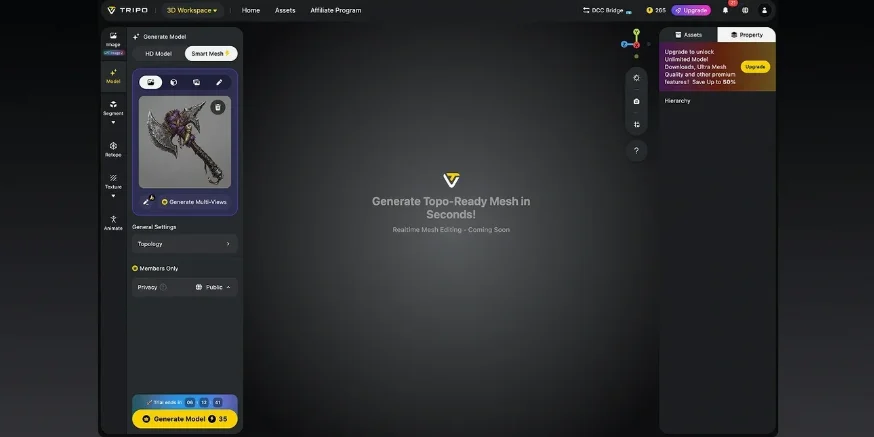
Generate Your 3D Model
Tripo analyzes your image and creates a 3D model in seconds, fast enough for iteration and precise enough for real work.
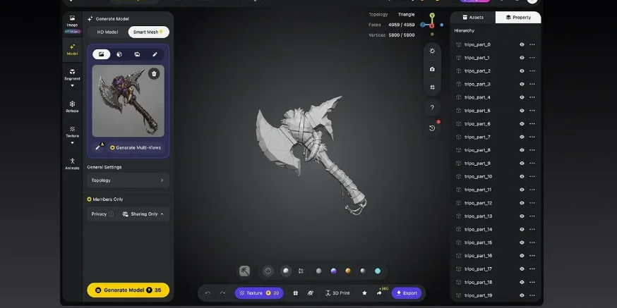
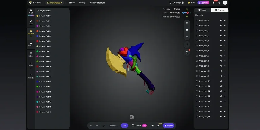
(Optional) Enhance
Refine your result with textures, rigging, animation, or part separation depending on your workflow.
Download and Use Anywhere
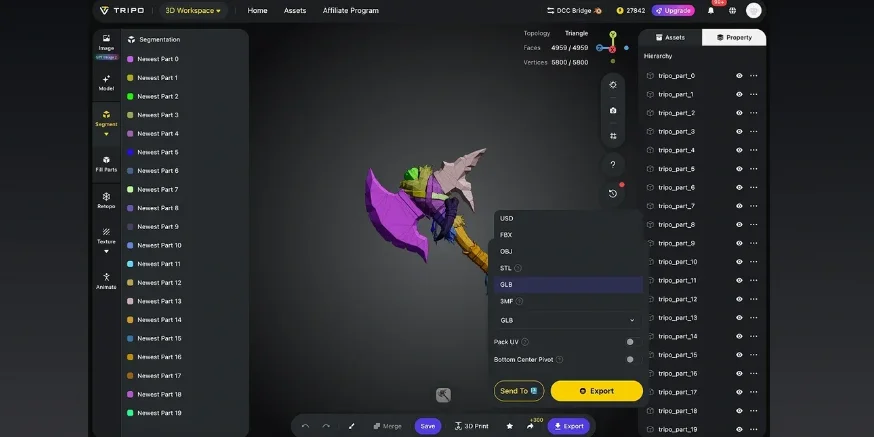
Export your 3D model in formats like STL, OBJ, and FBX for use in design, games, prototyping, and more.
Frequently Asked Questions
What is UV mapping used for?
The core function of UV mapping lies in dimensionality reduction, alignment, and size optimization. It establishes a one-to-one correspondence between 2D mapped pixels and 3D spatial coordinates, ensuring that materials integrate precisely and seamlessly onto the model surface without stretching.
What is the meaning of U and V in UV mapping?
The U-axis and V-axis represent the horizontal and vertical directions of texture mapping, respectively. Together, they form an orthogonal parameter coordinate system that describes the two-dimensional texture space.
What is the best UV mapping app?
The best UV mapping app depends on your workflow: Blender and Maya are strong all-in-one DCC choices, while RizomUV is the go-to specialist for precise manual and semi-automatic UV work. For AI-era speed, Tripo Smart Mesh stands out because it can automate UV mapping and help creators avoid much of the manual cleanup.
Why is UV mapping called UV?
UV mapping utilizes two independent texture coordinates, U and V, to map each point of the three-dimensional model onto the two-dimensional coordinates of the plane.
Conclusion
High-quality UV mapping is the fundamental prerequisite for achieving high-fidelity material textures. With generative AI advancing quickly, the AI Texturing feature in Tripo AI Studio can automatically complete texture generation and UV layout optimization. This significantly reduces the technical threshold and time cost of manual UV mapping, allowing creators to focus on creative concepts and artistic style.
