Creating an RC10 Bushing 3D Model: Workflow & Best Practices
Creating a precise RC10 bushing 3D model requires a solid understanding of mechanical design, careful measurement, and efficient workflow choices. In my experience, blending traditional modeling techniques with AI-powered tools like Tripo speeds up the process and improves accuracy, especially for iterative prototyping. This guide covers essential steps—from concept to production-ready mesh—and shares practical insights for both manual and AI-assisted approaches. Whether you're preparing for 3D printing, simulation, or integration into larger assemblies, these best practices will help you avoid common pitfalls and deliver reliable results.
Key takeaways:
- Accurate reference data is critical for mechanical parts like bushings.
- AI-powered tools streamline segmentation, retopology, and texturing.
- Efficient workflows reduce errors and speed up production.
- Retopology and mesh cleanup are essential for printability and simulation.
- Export settings must match target applications (game, CAD, print).
- Manual modeling offers control; AI tools boost speed and consistency.
Understanding RC10 Bushing Design Requirements
Key Measurements and Reference Materials
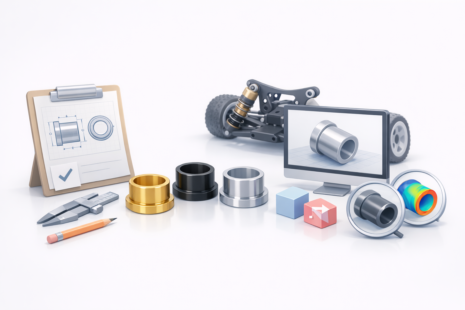
When modeling an RC10 bushing, I always start by gathering precise measurements—inner/outer diameter, length, flange size, and tolerances. Manufacturer datasheets, calipers, and high-resolution photos are indispensable. I also recommend referencing exploded diagrams or CAD files if available.
- Verify dimensions with multiple sources.
- Document tolerances for fit and function.
- Use physical samples for comparison when possible.
Common Challenges in Modeling RC10 Bushings
Mechanical bushings seem simple, but accuracy is crucial. Common issues I’ve encountered include misaligned holes, incorrect wall thickness, and overlooked fillets or chamfers. These can cause functional failures or print errors.
- Watch for subtle features (grooves, flanges).
- Double-check symmetry and axis alignment.
- Avoid overcomplicating geometry—keep it manufacturable.
Step-by-Step Guide to Modeling an RC10 Bushing
Initial Concept and Sketching Techniques
I usually start with a rough sketch, either on paper or digitally. This helps clarify proportions and feature placement before jumping into 3D. For bushings, simple cross-section sketches are often enough.
- Sketch key profiles: inner/outer circles, flanges.
- Annotate critical dimensions and tolerances.
- Use sketches as a blueprint in your modeling tool.
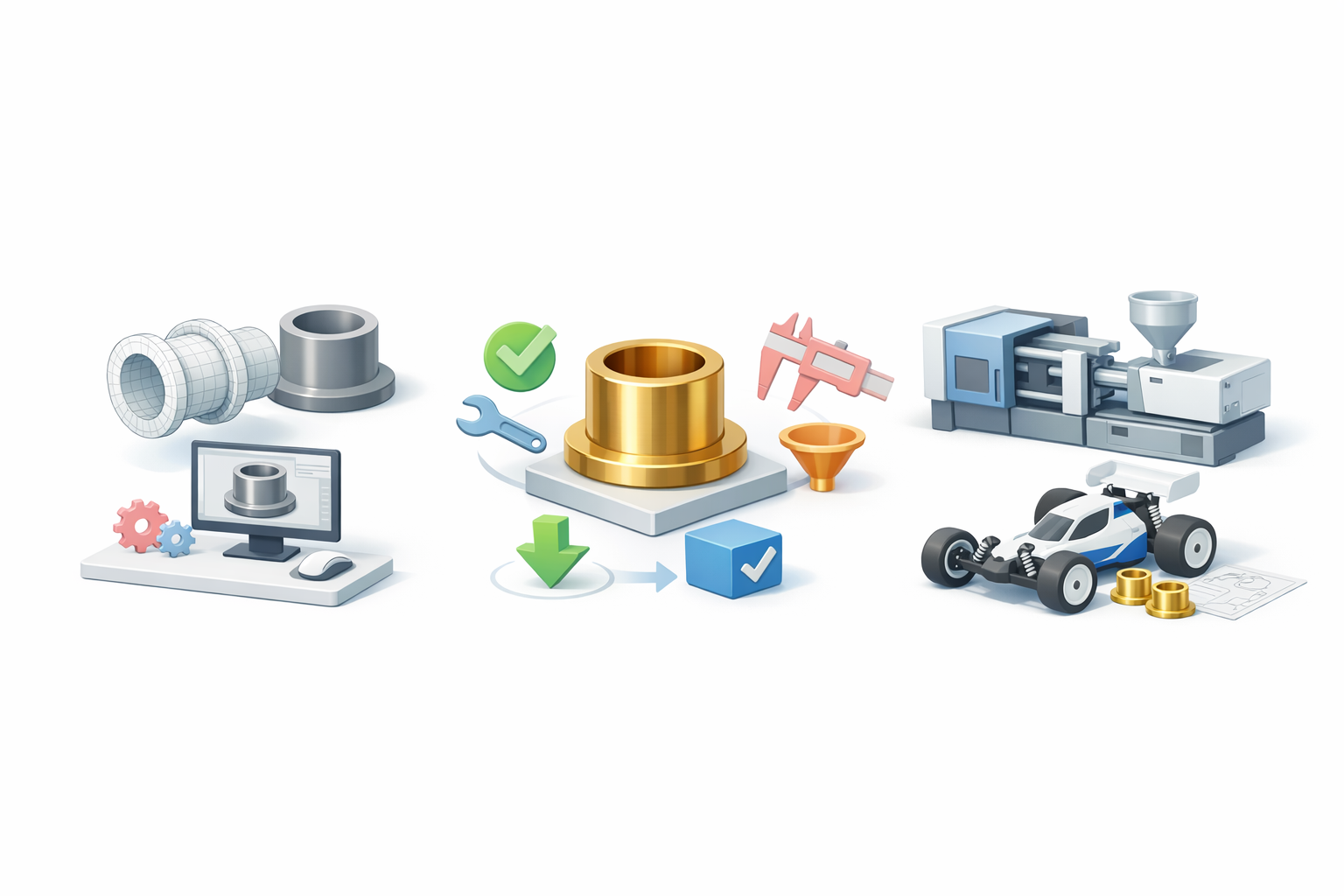
Efficient 3D Modeling Workflow
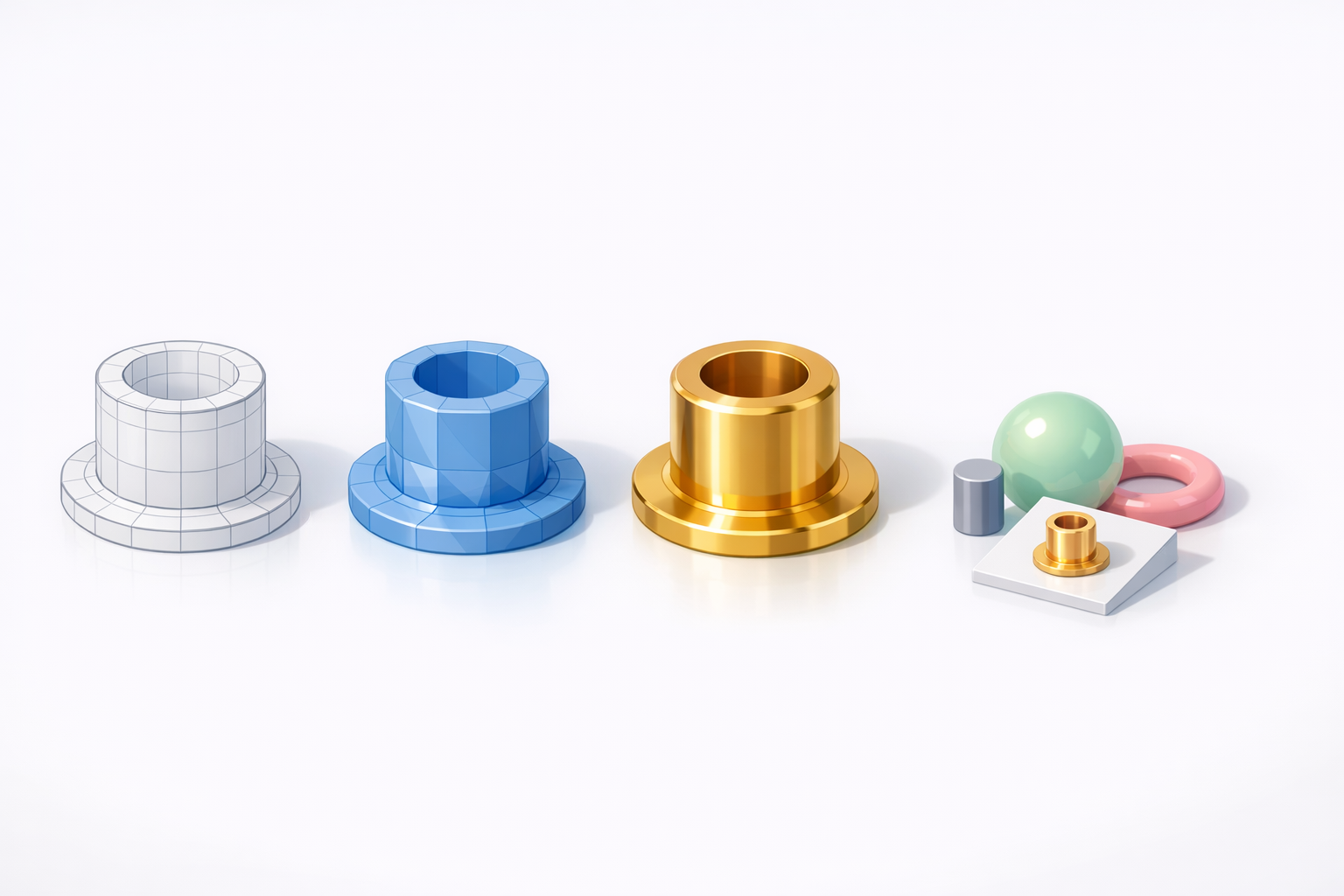
For cylindrical parts, I rely on parametric modeling—extruding profiles, adding fillets, and boolean operations. When using Tripo, I input sketches or reference images to accelerate segmentation and base mesh generation.
Workflow steps:
- Import reference sketch or image.
- Generate base geometry (extrude, revolve).
- Add details (flanges, grooves, holes).
- Use AI segmentation for complex features if needed.
- Validate dimensions with measurement tools.
Optimizing the Model for Production and Use
Retopology and Mesh Cleanup
After modeling, I always check mesh density and topology. For 3D printing, clean, quad-based meshes prevent slicing errors. Tripo’s retopology tools automate this, but manual tweaks are sometimes needed for critical surfaces.
- Remove unnecessary faces and n-gons.
- Ensure edge loops follow mechanical stress paths.
- Check for watertightness—no holes or non-manifold edges.
Preparing for 3D Printing or Simulation
Print-ready models need proper scale, orientation, and wall thickness. I export STL or OBJ files, making sure units match the printer’s requirements. For simulation, I optimize mesh resolution and assign material properties.
- Set wall thickness above minimum printable limits.
- Orient for minimal support and best surface finish.
- Export in compatible formats (STL for print, FBX for simulation).
Texturing, Exporting, and Integration Tips
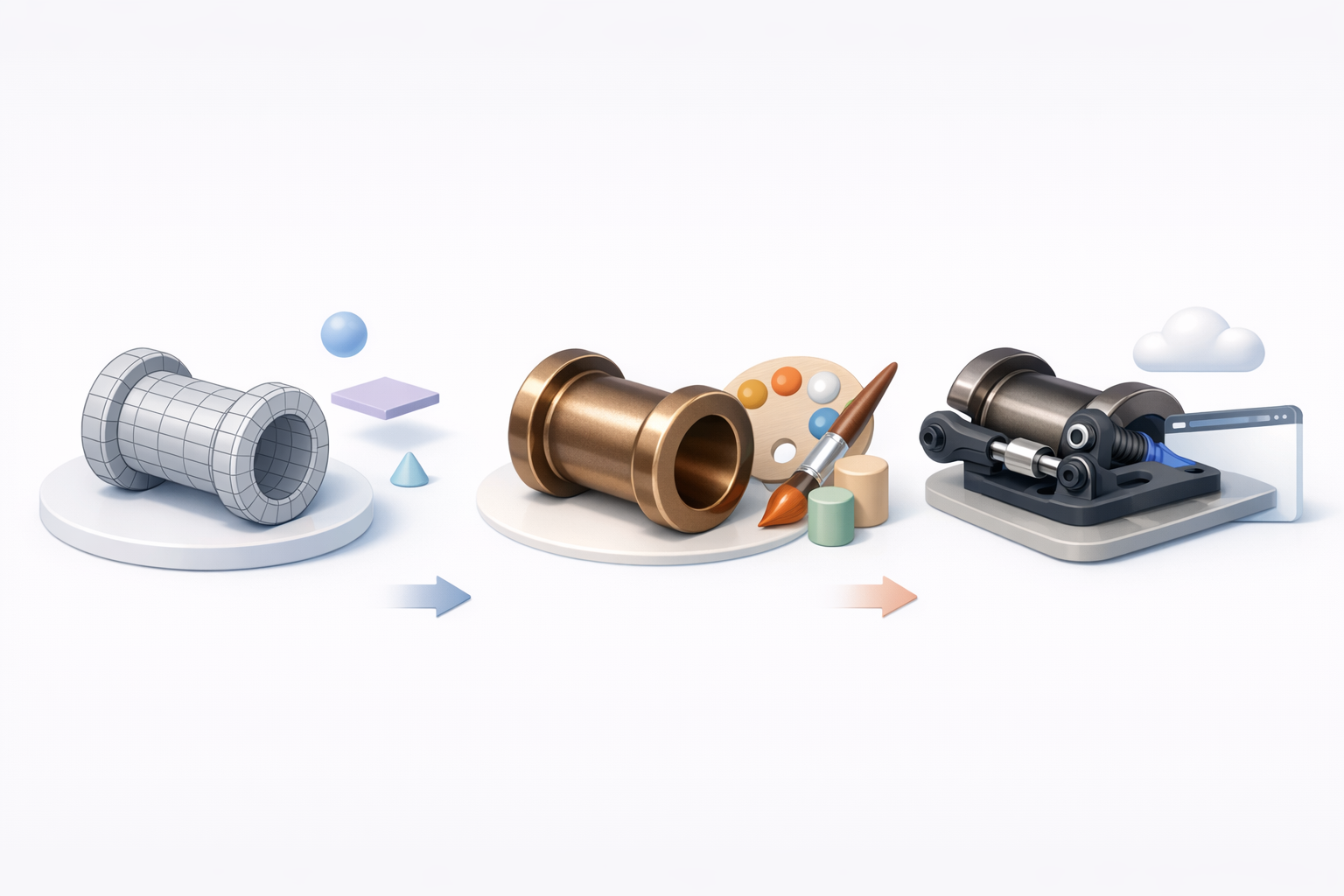
Applying Realistic Textures and Materials
For visualizations or game assets, adding realistic materials boosts credibility. I use Tripo’s smart texturing tools to quickly assign metal, plastic, or composite shaders. For mechanical parts, keep textures simple and avoid excessive wear marks.
- Use PBR materials for realism.
- Match textures to real-world reference.
- Avoid over-detailing—function is priority.
Export Settings for Various Applications
Export settings depend on end use. For CAD, maintain high precision; for games, optimize polycount and UVs. Tripo’s export presets help, but I always double-check scale and axis orientation.
- Select format based on workflow (STEP, STL, FBX, GLTF).
- Check units and axis alignment.
- Bake textures if needed for real-time applications.
Comparing AI-Powered and Manual Modeling Approaches
When to Use AI Tools for Bushing Models
In my experience, AI tools like Tripo shine when speed and repeatability matter—batching variants, automating segmentation, or retopology. For highly custom or complex bushings, manual modeling offers more control.
- Use AI for rapid prototyping and bulk asset generation.
- Switch to manual for intricate, highly-specific features.
- Combine both for best results.
Lessons Learned from Real-World Projects
Across multiple projects, I’ve found that blending AI and manual workflows yields the most reliable models. AI accelerates routine tasks, but hands-on checks ensure accuracy and manufacturability.
- Always validate AI-generated models against physical requirements.
- Don’t skip manual review—especially for functional parts.
- Iterative testing (print, fit, simulate) uncovers hidden issues.
Conclusion:
Whether you’re modeling RC10 bushings for racing, simulation, or manufacturing, leveraging both AI-powered and traditional workflows delivers speed and precision. Careful planning, measurement, and mesh optimization are key to production-ready results.


