Creating a Husky Ratcheting Screwdriver End Cap 3D Model: Expert Workflow
Designing a production-ready 3D model of a Husky ratcheting screwdriver end cap requires a blend of careful observation, precise modeling, and efficient use of modern tools. I’ve streamlined this process to minimize technical hurdles, focusing on practical steps that deliver clean, functional results—whether for prototyping, visualization, or integration in larger assemblies. This guide is for designers, engineers, and creators looking to model small mechanical parts with a professional finish, using both traditional and AI-powered workflows. My approach emphasizes accuracy, speed, and editability, reflecting lessons learned from real-world projects.
Key takeaways
- Gather precise references and measurements before modeling.
- Block out the basic shape, then add functional and aesthetic details.
- Use retopology and segmentation to keep geometry clean and editable.
- Apply realistic materials and textures for a production-ready look.
- Export with the right settings for your target platform and test fit in context.
- AI-driven tools like Tripo can accelerate routine steps, but manual refinement is still essential for critical tolerances.
Overview and Key Considerations for 3D Modeling Screwdriver End Caps
Understanding the Husky Ratcheting Screwdriver Design
Before modeling, I always study the screwdriver’s design to understand how the end cap interacts with the ratcheting mechanism and handle. The end cap often houses springs, detents, or retention clips—features that must be modeled accurately for functional prototypes or visualizations. I pay particular attention to how the cap snaps or screws into place, as this affects both geometry and tolerances.
Checklist:
- Identify locking and alignment features.
- Note any undercuts or complex shapes.
- Consider how the end cap is assembled/disassembled.
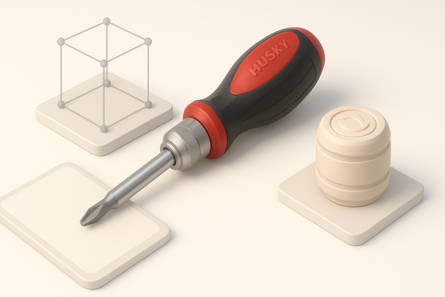
Essential Measurements and Reference Gathering
Accurate reference gathering is non-negotiable. I use calipers for physical measurements and supplement with high-res photos from multiple angles. If a physical sample isn’t available, I source technical drawings or user manuals.
What works for me:
- Photograph the part next to a ruler for scale.
- Measure outer diameter, inner diameter, lip thickness, and any slots or tabs.
- Annotate reference images for quick lookup during modeling.
Step-by-Step Workflow: Modeling the End Cap
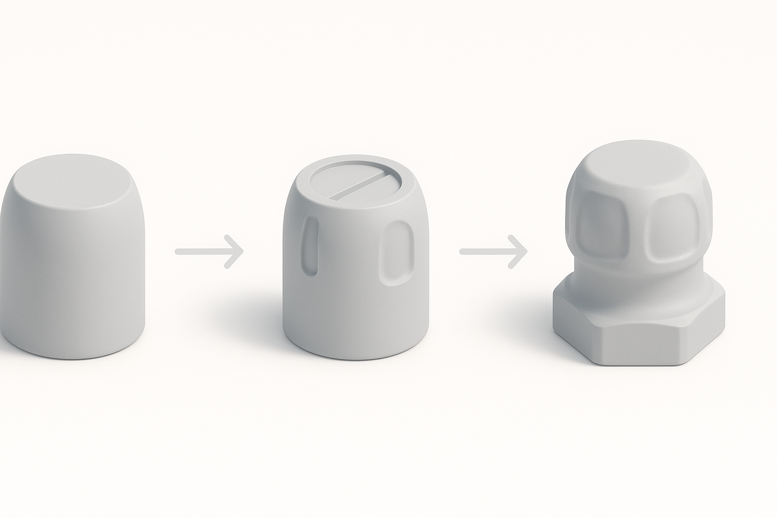
Blocking Out the Basic Shape
I start with simple primitives—usually a cylinder for the main body. Blocking out the overall proportions first helps avoid wasted effort on details that might need reworking later. In Tripo, I input rough dimensions and let the tool generate an initial mesh, which I refine manually.
Steps:
- Create a cylinder matching the outer diameter.
- Add a second cylinder for the inner cavity (boolean or shell operation).
- Adjust height and wall thickness to match references.
Adding Details and Functional Features
Once the base shape is set, I add functional elements like tabs, slots, or knurling. For features like ratcheting detents or retention clips, I model them as separate meshes for easy adjustment.
Tips:
- Use symmetry and array modifiers for repeating features.
- Keep functional details as separate objects until the design is finalized.
- Leverage Tripo’s segmentation tools to isolate detail areas for quick edits.
Optimizing Geometry: Retopology and Segmentation Best Practices
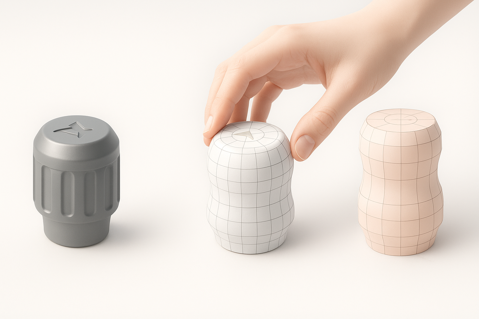
Efficient Retopology for Production-Ready Models
Clean topology is essential for both 3D printing and real-time applications. I use automated retopology tools for initial cleanup, then manually adjust edge flows around critical features.
My workflow:
- Run auto-retopo for the main body.
- Manually retopologize around clips, threads, or snap-fits.
- Keep quads where possible for easy editing and subdivision.
Intelligent Segmentation for Easy Editing
Segmenting the model into logical parts (e.g., cap body, clip, decorative insert) makes later changes painless. Tripo’s intelligent segmentation helps me quickly isolate and edit features without affecting the whole mesh.
Pitfall to avoid: Don’t merge everything too early—retain editable groups until the final export.
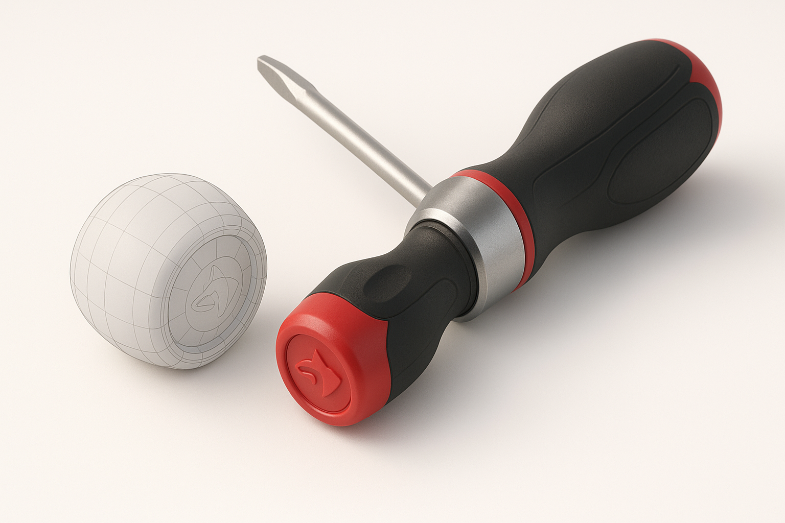
Texturing and Material Application Tips
Selecting Realistic Materials and Colors
For realistic renders, I gather reference images of the actual Husky screwdriver. The end cap is typically made of textured plastic with subtle color variations. I sample colors directly from photos and use PBR materials for authenticity.
Checklist:
- Assign base colors to each segment.
- Choose materials with appropriate roughness and reflectivity.
- Use normal maps for fine surface detail, like knurling or logos.
Applying and Refining Textures
I unwrap UVs carefully to avoid stretching, especially on cylindrical surfaces. In Tripo, I use built-in texture painting for quick iterations, then refine in a dedicated texturing app if needed.
What I’ve found:
- Bake AO and curvature maps for more realistic shading.
- Use decals for logos or small text, rather than modeling them.
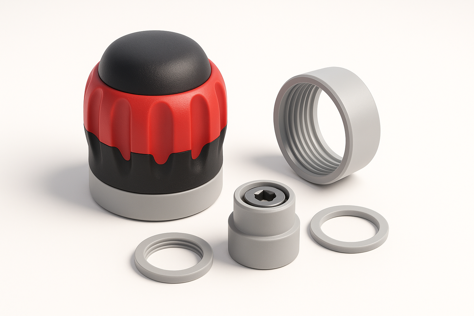
Exporting, Testing, and Integrating the 3D Model
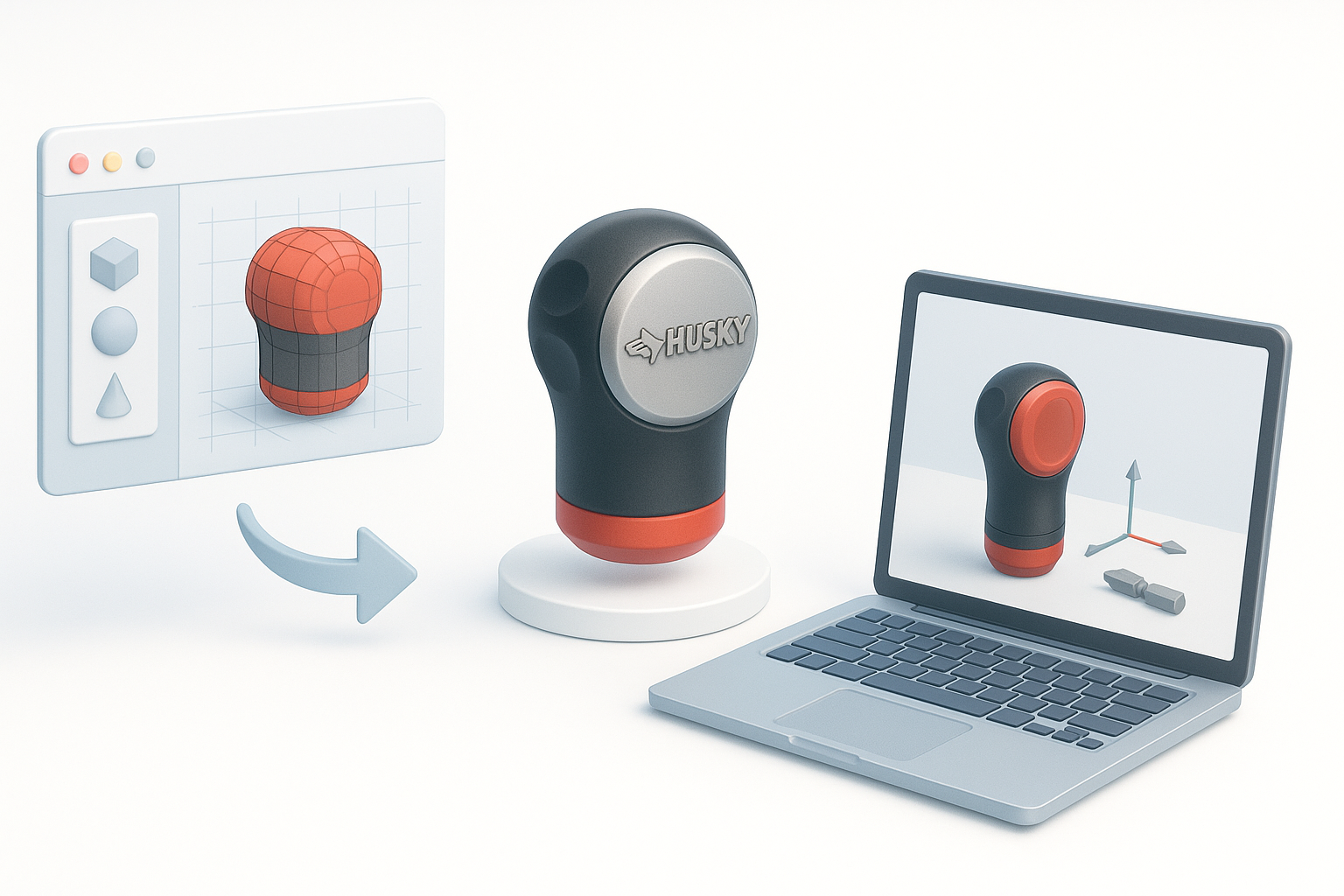
Export Settings for Various Platforms
Export settings depend on the target platform (CAD, game engine, 3D print). I typically use OBJ or FBX for general use, and STL for printing.
Best practices:
- Check scale and units before export.
- Apply all transforms and freeze scale.
- Export with logical part names for easy assembly.
Testing Fit and Function in Virtual Assemblies
I always test the end cap in a virtual assembly with other screwdriver components. This helps catch fitment issues before prototyping or release.
Steps:
- Import the cap into the full screwdriver assembly.
- Check for interferences and clearances.
- Adjust as needed, then re-export.
Comparing AI-Powered and Traditional 3D Modeling Approaches
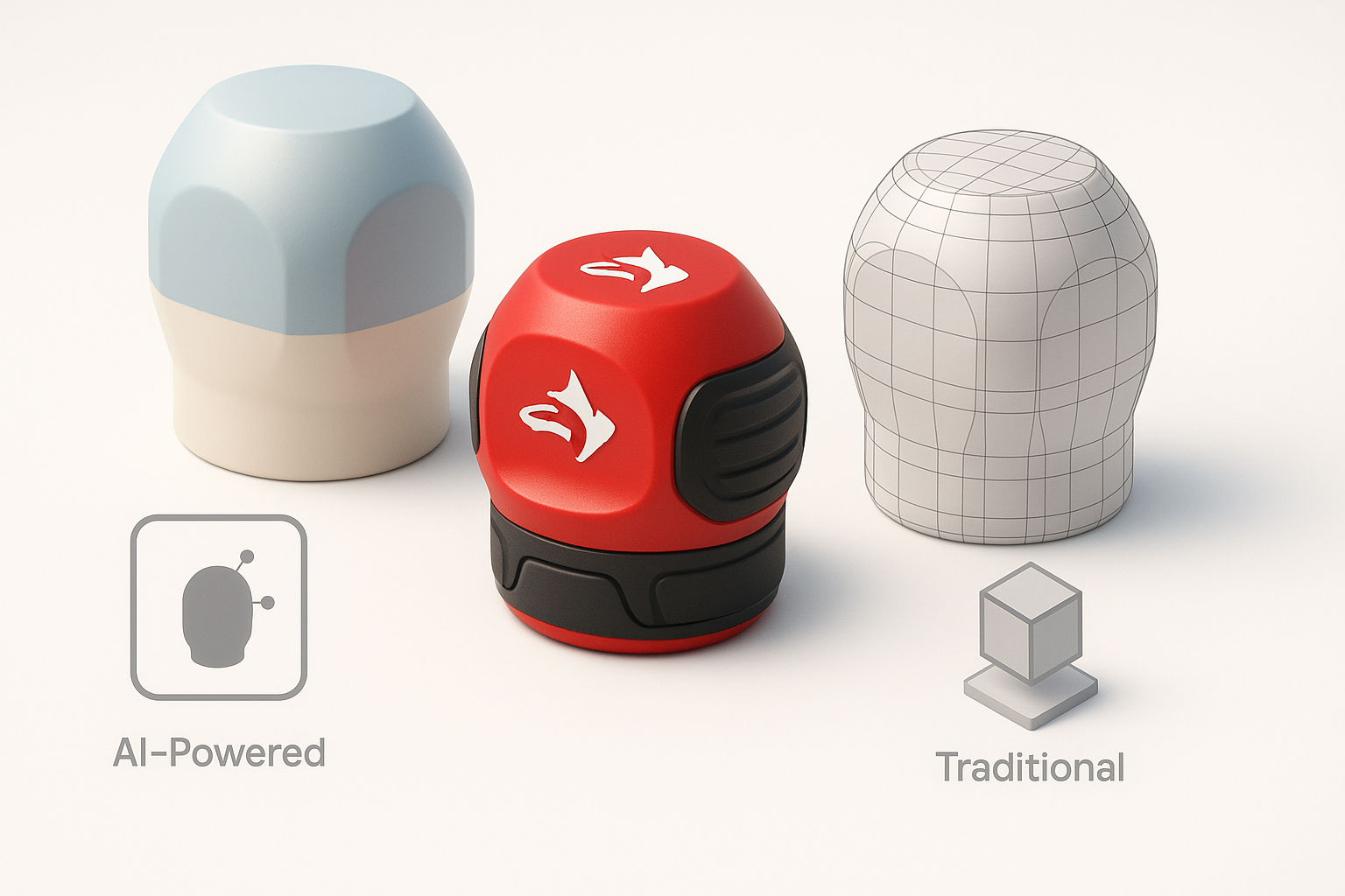
Benefits of Using AI-Driven Tools for Rapid Prototyping
In my experience, AI-powered tools like Tripo dramatically speed up repetitive or technical steps—blocking out shapes, auto-retopology, and segmentation. This lets me focus on design intent and detail, rather than wrestling with topology or UVs.
When I use AI:
- Quick iterations for concept validation.
- Generating base meshes for further manual refinement.
When to Choose Manual Modeling Techniques
For critical tolerances, complex features, or highly stylized details, I still rely on manual modeling. AI tools can get close, but nothing beats hands-on control for fine adjustments and custom geometry.
Pitfall: Don’t skip manual checks—AI-generated geometry may need cleanup for production use.
My Lessons Learned and Expert Tips for Screwdriver Component Modeling
Common Pitfalls and How to Avoid Them
- Overcomplicating geometry: Start simple and add detail only as needed.
- Ignoring tolerances: Always account for manufacturing or assembly clearances.
- Merging parts too early: Keep components separate for as long as possible.
Personal Workflow Enhancements and Time-Saving Tricks
- Use reference images as viewplane overlays while modeling.
- Leverage AI segmentation for rapid edits, but always review results manually.
- Save incremental versions—sometimes a previous iteration is the quickest fix.
Modeling a Husky ratcheting screwdriver end cap is a rewarding exercise in precision and workflow efficiency. With the right blend of AI-powered tools and manual craftsmanship, I consistently achieve production-ready results—quickly, accurately, and with minimal friction.